Wednesday July 15th, 2026
Blender Tips & Tricks
Last updated: May 31st, 2026
Blender is a professional, open-source 3D computer graphics application used for modeling, sculpting, animation, rendering, visual effects, simulation, video editing, and game asset creation. This section includes a wide range of powerful, and sometimes underutilized features that can significantly streamline your workflow, enhance productivity, and improve the overall quality of your projects.
Recent Updates
May 31st, 2026
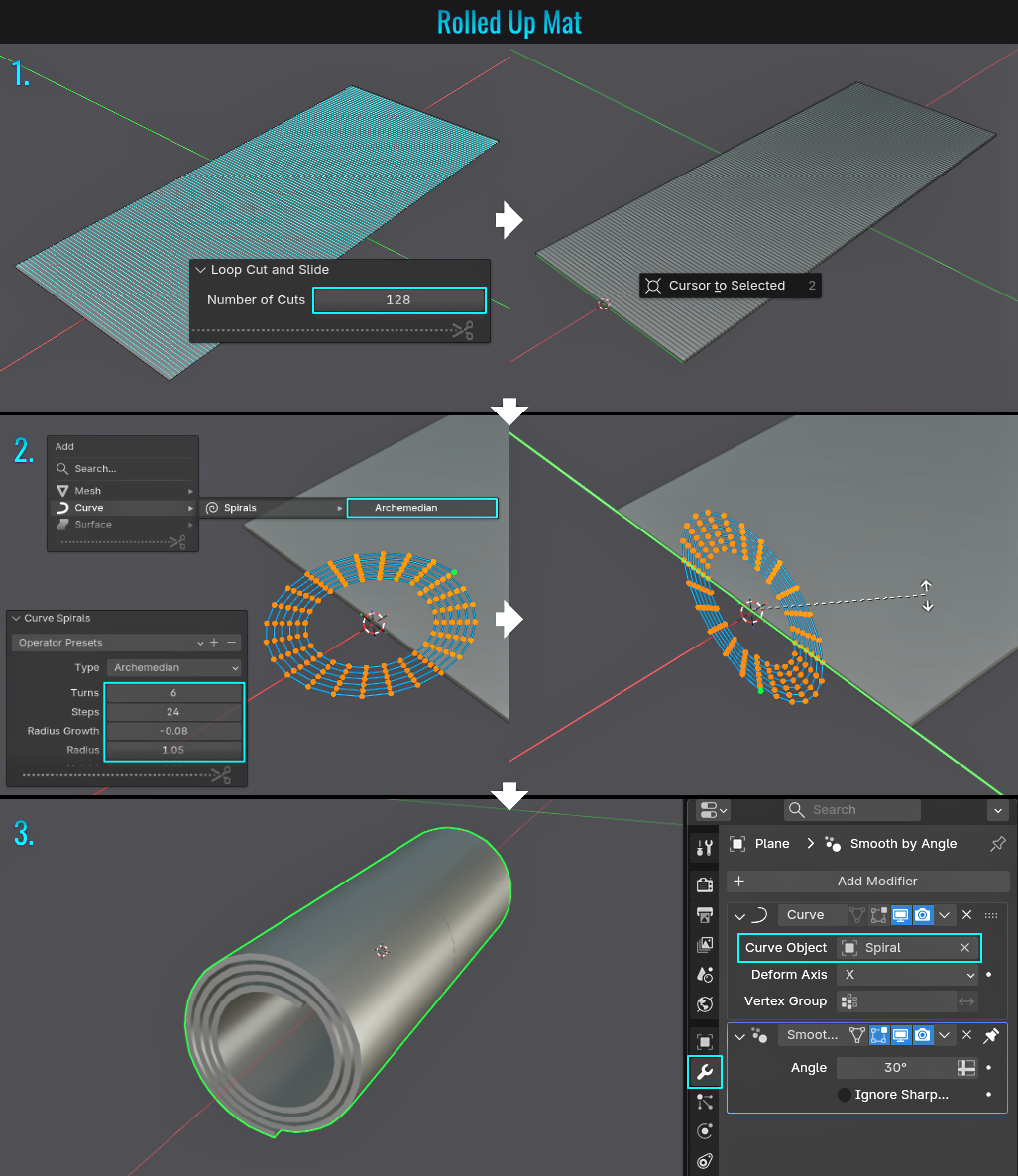
Added tip #293: Rolled Up Mat
May 23rd, 2026
April 5th, 2026
Added tip #291: Swap Viewports
December 31st, 2025
December 29th, 2025
November 2nd, 2025
Subject
Description
- Camera Align To Face
Shift + Numpad 7 to align camera to selected faces (you'll need to press Numpad 5 afterwards and orbit scene a bit to force regular perspective again - as when in Shift + Numpad 7 mode, the camera is an orthographic type).
- UV Editor 2D Cursor
Make use of the 2d cursor in UV editor by holding Shift and right-click (or right-click drag) to position the 2d cursor! Press the . key (not on the Numpad) to bring up the Pivot Point pie menu and choosing 2d Cursor, as it can become a handy "anchor point" for rotations and scaling UV islands for example! Press Shift and right-click (or right-click drag) to position the 2d cursor!
- UV Editor Workspace
Need to jump between modeling and UV'ing assets? Stay in the UV workspace to model and UV using Ctrl + Space to maximize whichever view (3d Viewport or UV editor) the mouse cursor is hovering over! This applies to any Blender window!
- Make Selections Circular
There are a couple of ways to make a selection circular:
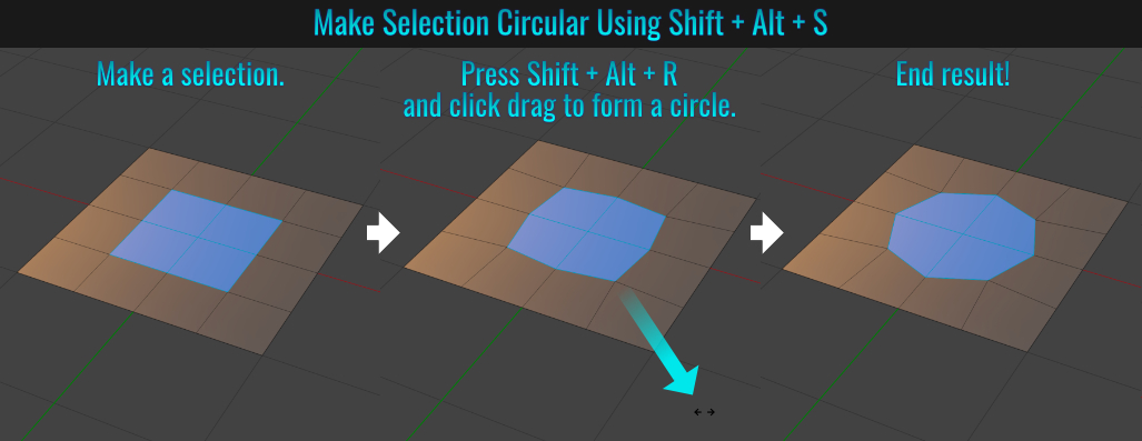
Method 1
Select some faces, press Shift + Alt + S and left-click drag to force selection into circular formation. By extension, you can also press 1 after the aforementioned keys instead of dragging the mouse to instantly form the circle!
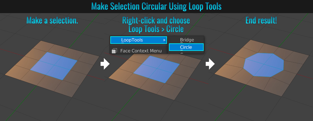
Method 2
Install the Loop Tools Add-on. After selecting some faces, right-click and choose Loop Tools > Circle to force a prime and proper circle from a selection!
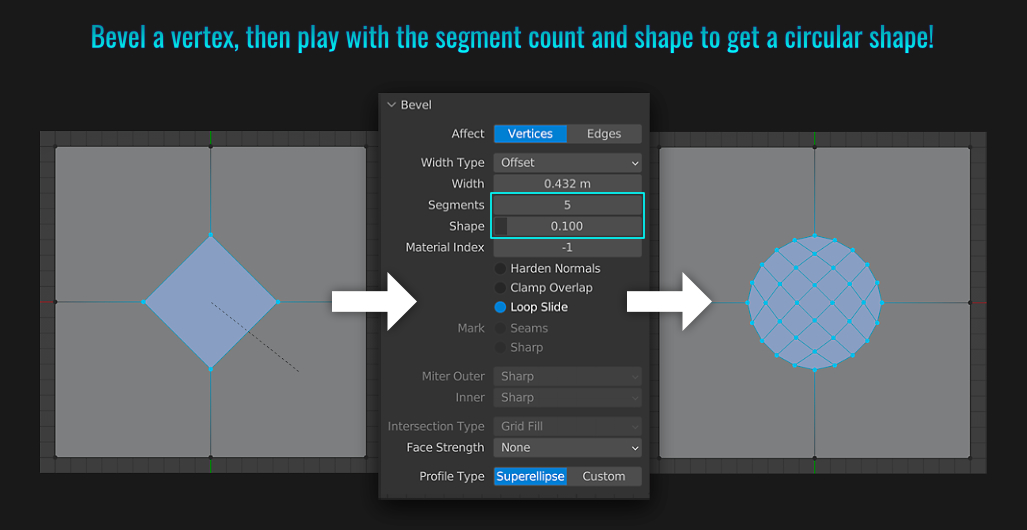
Method 3
Simply perform a bevel on a vertex (using either Ctrl + Shift + B - or- Ctrl + B then V). Once you left-click to finalize the bevel, open the Bevel Operator panel located in the bottom-left corner of the viewport and
adjust the Segment count as well as the Shape parameter to establish a circular shape!
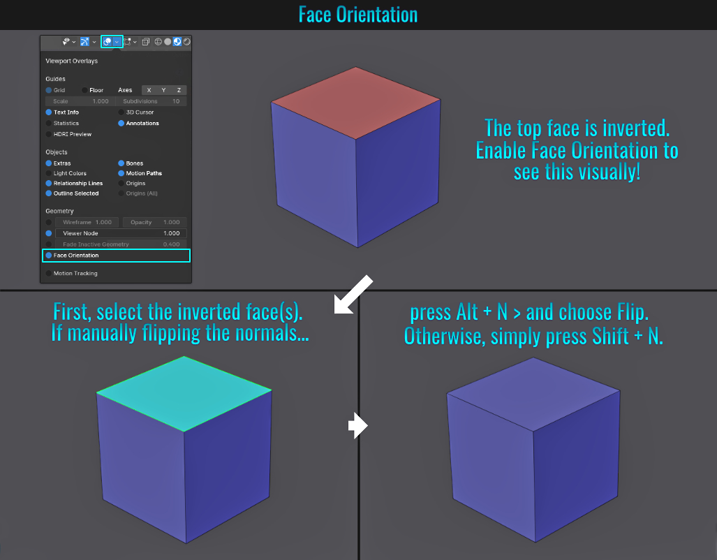
One way to find inverted faces (or if you simply don't want to view the back side of face normals), make use of face orientation and
backface culling.
Face Orientation
Face orientation can be found in Show Overlays (simply enable this near the bottom). In the event you need to flip normals, with the inverted face(s) in question selected and from the viewport menu, either choose:
- Mesh > Normals > Flip from the viewport menu (Alt + N > Flip) - or -
- Recalculate Outside (Shift + N - normals face outwards automatically)
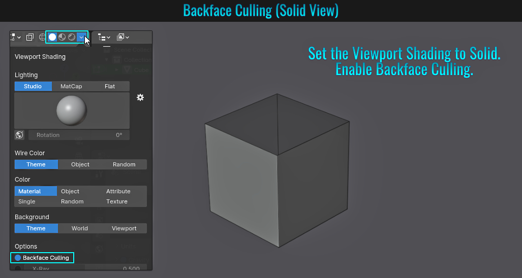
Backface Culling
What some people might not realize is that backface culling is actually split into two different areas within Blender. Using the same example as above, let's quickly examine how these work!
- Viewport Shading - Solid
When the 3d viewport is set to this mode, the way to enable backface culling is via the shading dropdown menu.
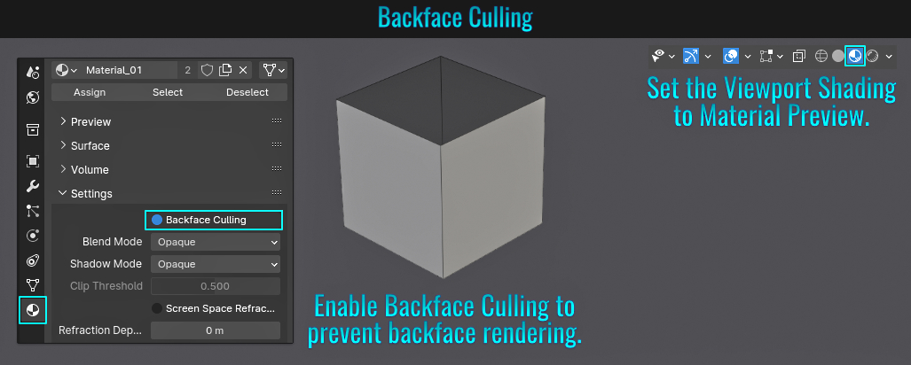
- Viewport Shading - Material Preview
Once a material is applied to your mesh (and you are in the Material Preview mode), Backface Culling can be found in Material Properties > Settings panel. Simply enable this to see that back faces are no longer rendered within the viewport!
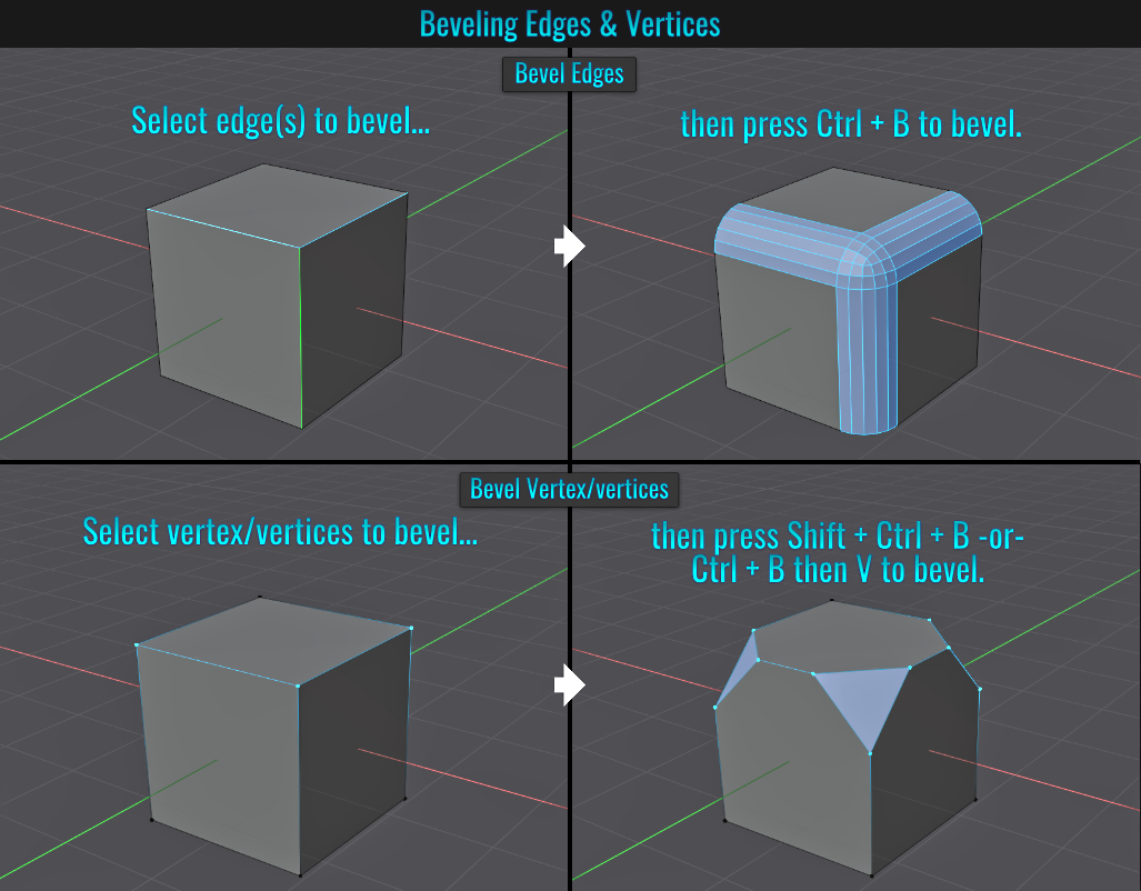
- Beveling
To bevel a face or edge, simply press Ctrl + B. To bevel a vertex, press either:
- Shift + Ctrl + B - or -
- Ctrl + B then V
It's important to note that when in vertex select mode with vertices selected, oddly enough, under the hood the bevel operator itself is not beveling vertices by default, but rather
edges instead! As a result, if you only have a single vertex (or multiple vertices that don't share the same edges) selected, Ctrl + B does nothing, as there no edge information for the beveling operator to work with! When two (or more) vertices
sharing the same edge(s) are selected, the corresponding edge(s) are beveled!
When you press Shift + Ctrl + B instead, the added shift key modifier puts the beveling operator into beveling vertex mode automatically! Alternatively you can
simply press Ctrl + B and then toggle the beveling operator into vertex mode by pressing V afterwards! When a bevel operation is live, V will always toggle from face/edge to vertex beveling or vice versa!
Adjusting Bevels
Once you start beveling, notice at the very bottom of the viewport UI that there is a list of possible shortcuts!
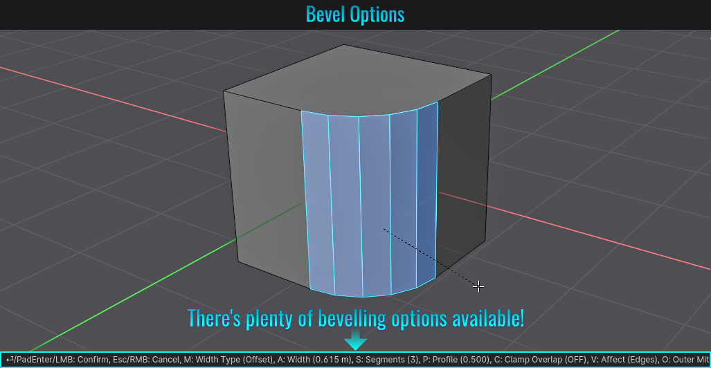
Let's examine a some of the more popular ones that you might find really useful during a live beveling operation!
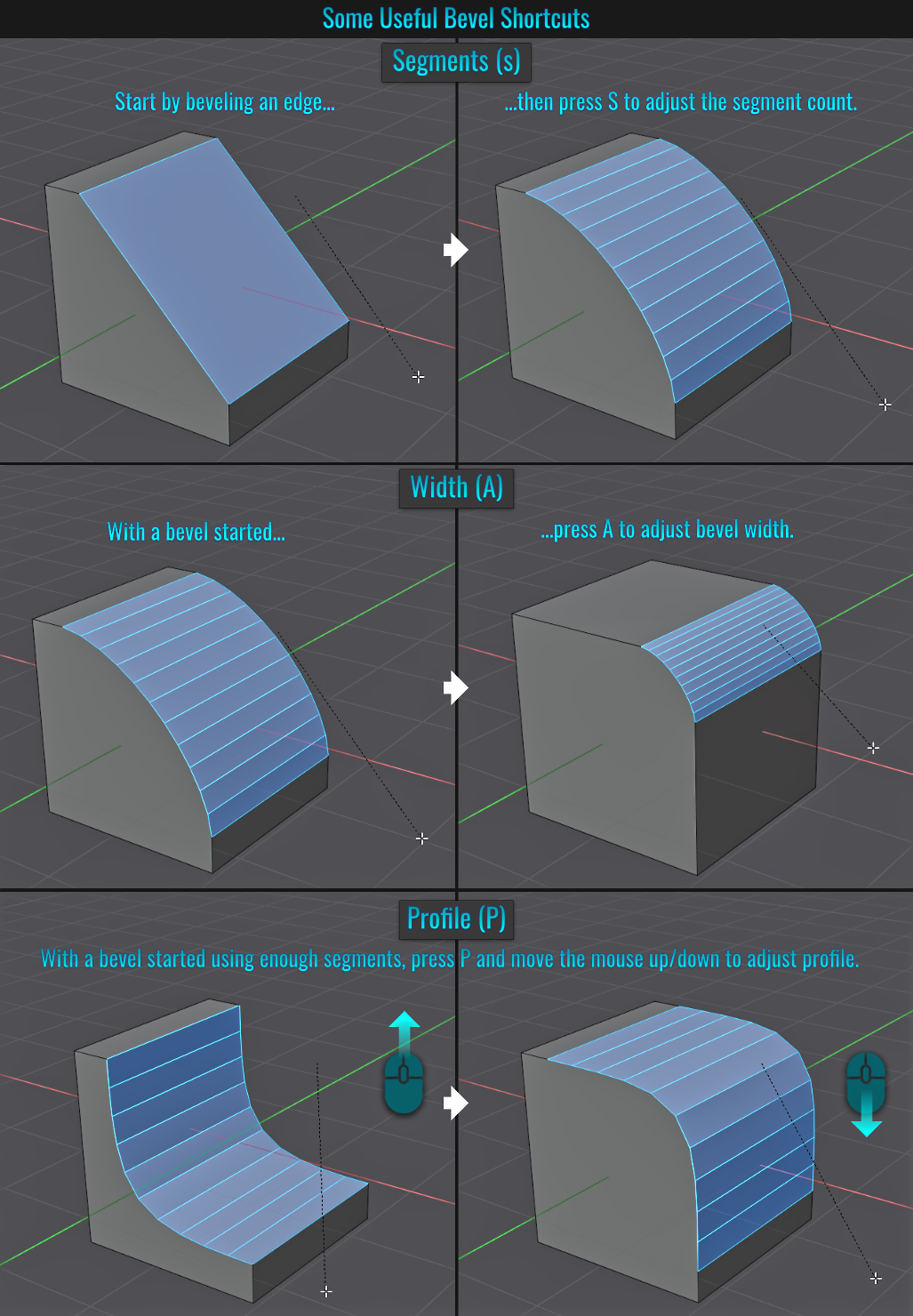
- Segments - Shortcut: S
- There are a few ways to increase/decrease bevel segments:
- The first is by scrolling the mouse wheel.
- The second is interactive mouse movement (left/right - even works with up/down).
- The third (which is much less known) is to type in a segment count.
- There are a few ways to increase/decrease bevel segments:
- Width - Shortcut: A
- Interactive mouse movement (left/right) will increase/decrease the bevel's width respectively.
- Interactive mouse movement (left/right) will increase/decrease the bevel's width respectively.
- Profile - Shortcut: P
- With enough segments, this will adjust the profile! Moving the mouse left will increasingly form the bevel concave while moving to the right will lean towards a convex form (both will lead to sharp, 90 degree angles once the profile hits its limit).
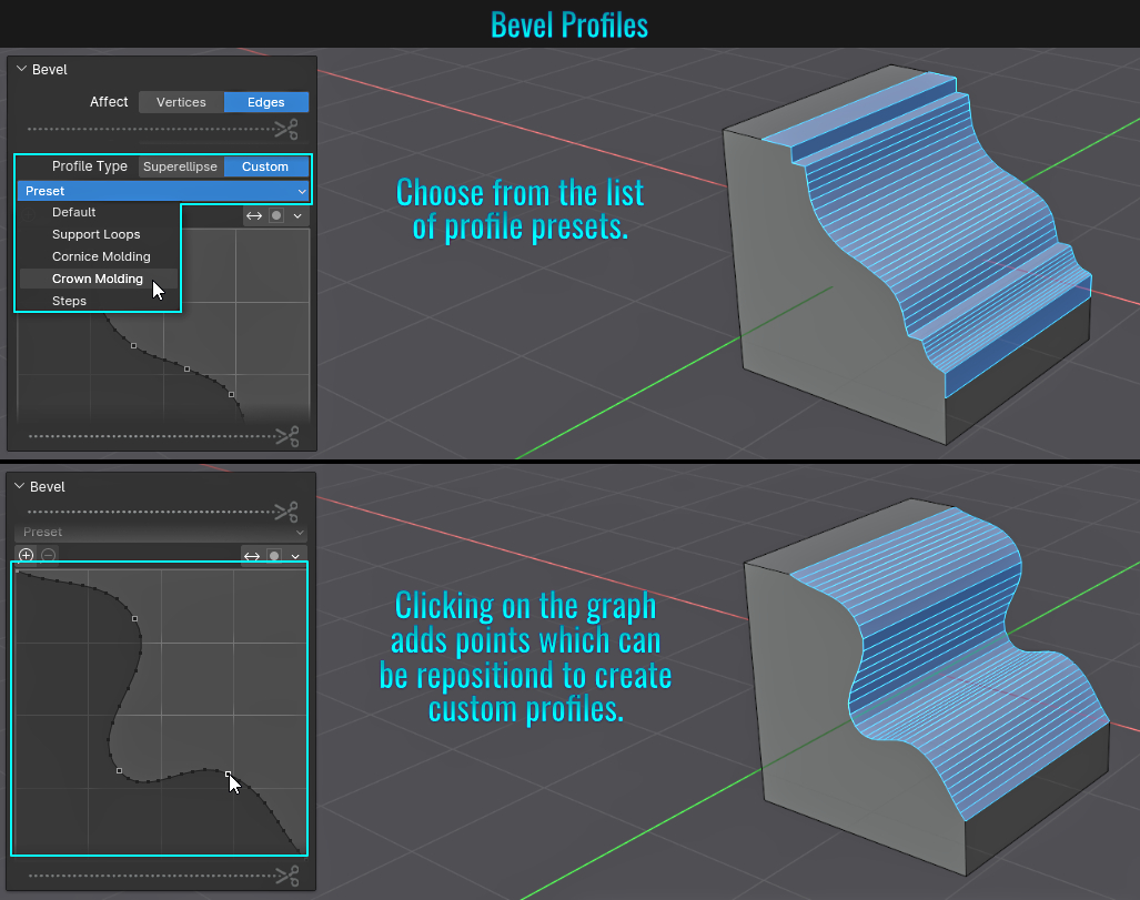
Bevel Profiles
Once a bevel is performed, open up the Bevel operator panel in the lower left hand corner of the viewport and from within the Profile Type section, click on Custom. Here, you have a few options. You can either select a custom profile from the Preset
dropdown menu, or click on the line within the profile to add control points that you can move around to create your own profile!
- General Moving, Scaling & Rotations
- Pressing G to move globally - double press X, Y, or Z for local transforms.
- Press G twice to slide a vertex along its edge.
- Press Shift + V to slide a selection either left/right or up/down.
- Pressing G then Shift + (X, Y, or Z) eliminates that axis from movement - so G then Shift + Z means moving in only the X & Y axes.
- At anytime while the grab tool is enabled, pressing Shift + Tab constrains the movement to incremental snapping!
- If no Transform, scaling or rotations have been applied to a mesh, pressing Alt + R resets rotation, Alt + S resets scale and Alt + G resets move.
- Pressing R twice gives free rotation.
- Select Element
Press L with the mouse cursor hovering over a mesh in Edit mode selects all contiguous shared elements while pressing Shift + L deselects it!
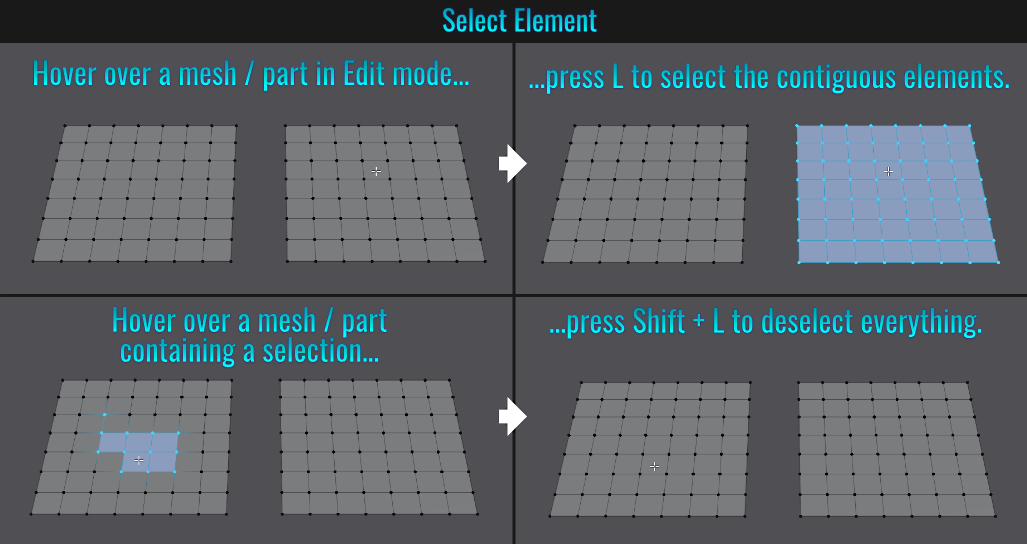
Additionally, if you need to select all contiguous shared elements via a selection, simply select an element, then press Ctrl + L!

- Snapping Vertices
- Traditionally, when snapping vertices together (enable the snap tool in Vertex mode with Closest set for the Snap with feature), simply select the source vertex, press G then click-drag onto the target vertex, then release mouse button to finalize the snapping operation!
- However, while not enabling the snap before hand, you can snap vertices together by selecting the source vertex, then while hovering the mouse cursor over the target vertex, press G and enable the snap only temporarily while pressing Ctrl and left-click! The source vertex will automatically snap to the target vertex! No click-dragging necessary!
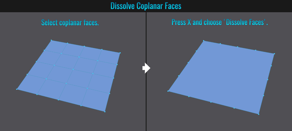
- Face Cleanup
Fast way to remove edges on coplanar faces is to select them, press X and choose Dissolve Faces (manual re-triangulation will be required afterwards as there will be no triangles, hence the clean up).
- Wireframe/X-Ray Toggle
When working with models, sometimes you might need to jump between different modes that include wireframe and x-ray (this assumes x-ray wasn't previously disabled - otherwise it won't be toggled). Both have their advantages that allow you to see through your
geometry!
Wireframe / X-Ray
Shift + Z puts the viewport into Wireframe and X-Ray mode and toggles between this and the current selected viewport mode outside these modes. This is handy to view mesh wire frames without extraneous visuals!
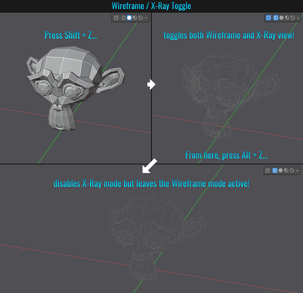
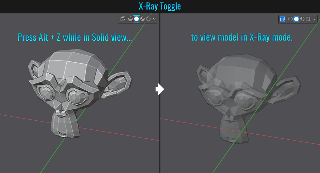
X-Ray Only
You can toggle between Solid viewport display mode and X-Ray mode by simply pressing Alt + Z!
- Select Similar
Want to select all faces with a specific set of circumstances (say select all faces that are coplanar for instance)? Select a face and press Shift + G to bring up the Select Similar menu! Below are some simple examples...
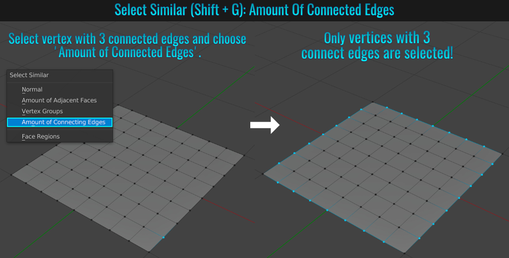
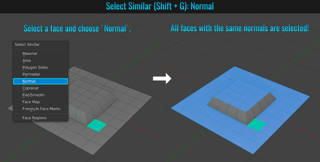
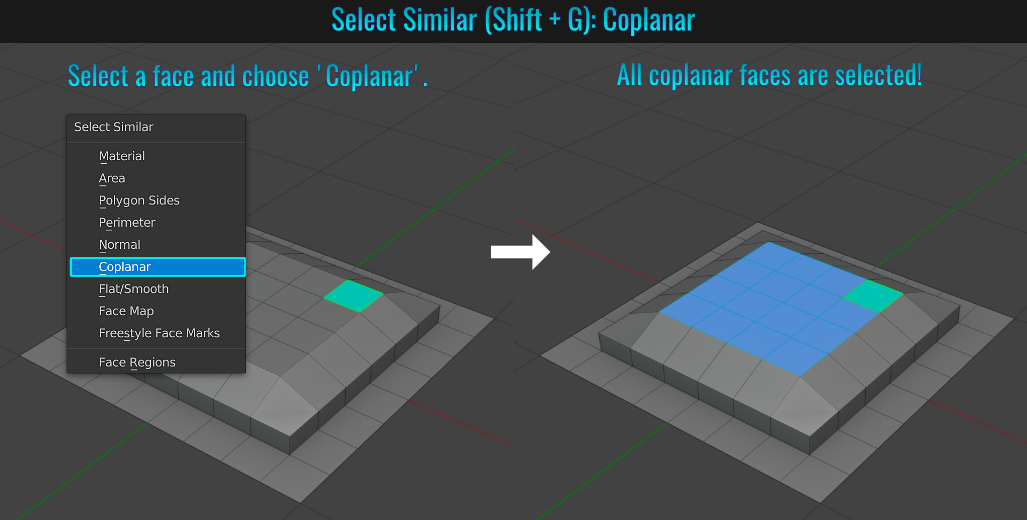
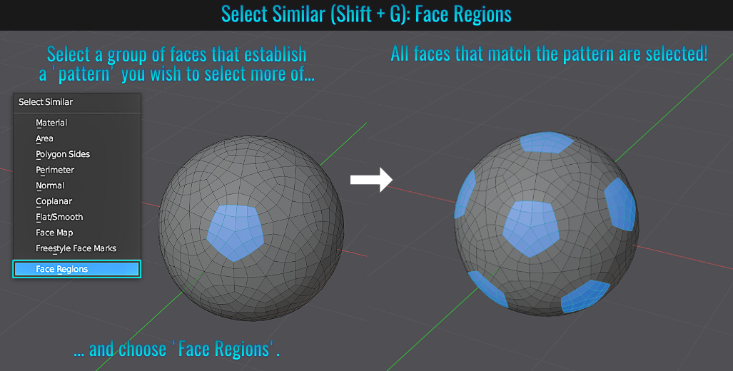
Experiment with other features in Select Similar, as it offers more functionally that what is discussed here!
- Duplicating & Instancing Meshes
Shift + D duplicates whatever object is selected.
Alt + D creates an instance instead!
To make an instanced object unique, you can simply go to the Object Menu and choose Relations > Make Single User > Object & Data.
- Extra Modelling Features
Make use of tools like shear, shrink/fatten and other useful buttons left side 3d viewport buttons while in Edit Mode (press T to hide or unhide them)!
 Spin Tool
This takes a selection and spins / duplicates it in a circle centered on the 3d cursor's location! In some cases it's easier to use the spin tool instead of setting up an array modifier along with an empty object to accomplish radial arrays. Enabling the 'Use Duplicates' option only duplicates the selected element without any faces connecting them! See the online documentation for more details.There appears to be no difference between this and the alternative Spin Duplicates function! Poly Build
Starting with flat polygon (like a plane for example), selecting an edge (blue edge highlights) and click-dragging it acts as an quad extrude. Ctrl clicking from an edge or vertex extrudes a triangle whileShift clicking over a polygon or vertex (red edge highlight) deletes it! This tool is very useful for vanilla, out of the box Blender retopology! Shrink/Fatten
Allows a selection to be either grown (fattened) or shrunk down by moving vertices along their normals This comes in handy when say needing to adjust a cup handle's thickness for instance. Push/Pull
The difference here is that the selection will be moved towards / away from the transform pivot point! Here is a video showcasing both options. Shear
Shear
This shears a selection on a mesh in the desired screen axis via little horizontal and vertical bar handles. See this example to better understand how this works. Add Cube
Enables the user to click drag and release a cube in the viewport (a la 3DS Max). Better yet, a cube can be added to an existing surface!
- Circle Select Sizing
Circle Select (pressing C) size adjustment is done while holding down left mouse button and using mouse scroll wheel. Right-click to exit circle select. Circle Select is useful for 'paint' selecting elements as opposed to clicking on each one individually or marquee selecting.
- Open Recent Files
Shift + Ctrl + O brings up the recent opened popup panel. Faster and more elegant than the traditional File > Open Recent method.
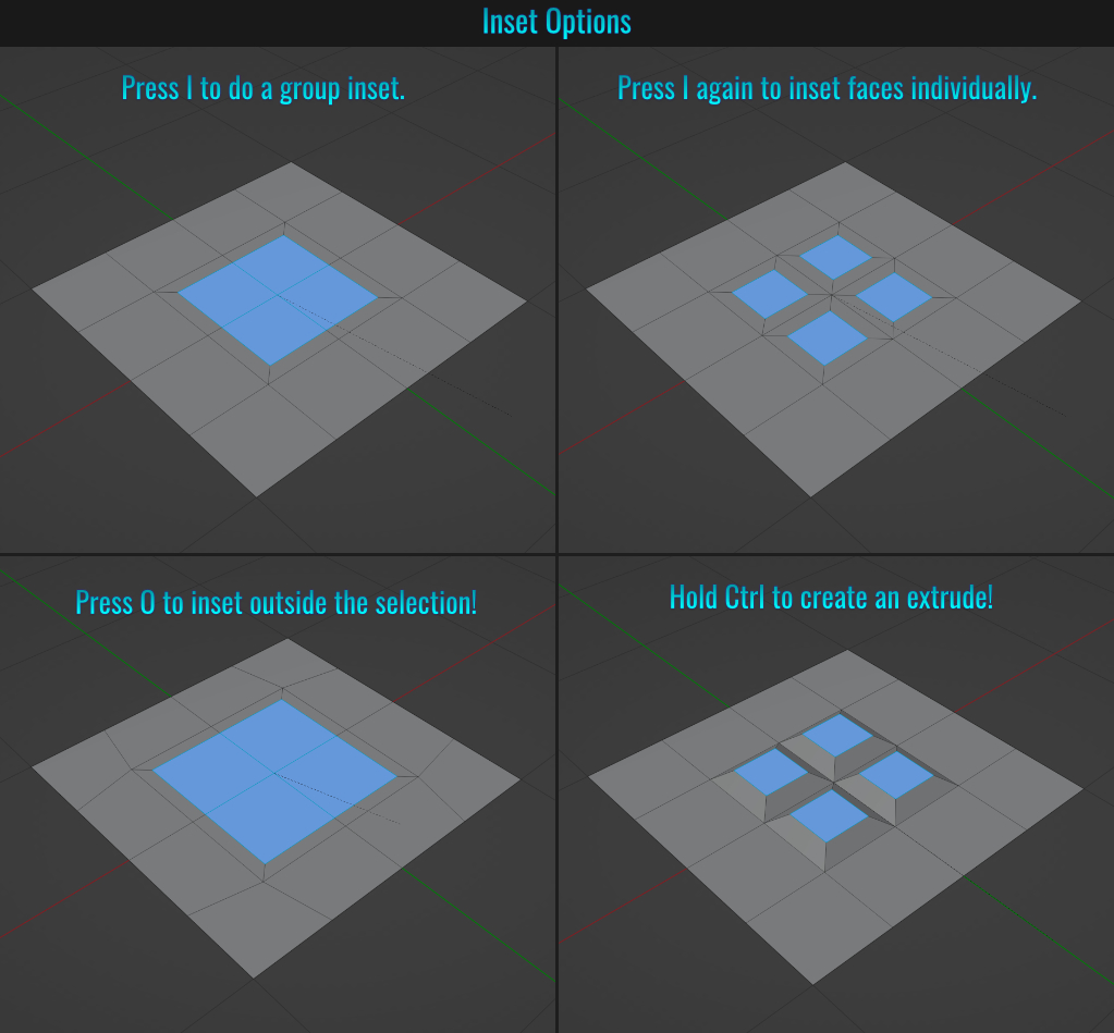
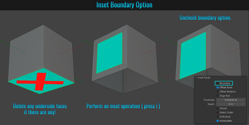
- Inset Options
In Blender, insets have multiple functionally that goes beyond the mere inset itself! With some faces selected:
- Press I to inset. This insets the entire selection as a single group (default behavior).
- Press I again insets all selected faces individually.
- Press O to inset outside the selected faces!
- Once an inset is live, hold down Ctrl and move the mouse left or right to create inner or outer extrudes respectively!
Use inset with the Boundary option unchecked to create doorways. Beforehand, ensure that there is no capped faces beneath!After selecting face and pressing I to initiate the inset tool, you can press B while the tool is active to set the boundary option!
- Knife Tool Features
Basic Usage
The Knife tool enables you to add custom cut lines to your geometry. Simply press K to enter the knife cutting mode and left click to insert cut points on the surface of the mesh and Blender will join these points with edges as you go (knife clicks on either side of
edge(s) will cut through them!) To finalize the cut, you can either simply press Space Bar or Enter.
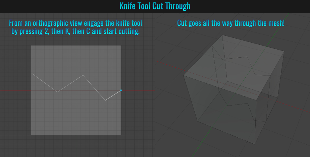
Cut Through
To cut through the whole mesh (example, from top through to the bottom via top view with Numpad 7 - the cut is view dependant), go into edge mode, press K to enter knife mode, and then C.
Now start cutting... it will go through the entire mesh!
Pause / Resume
You can "pause" the knife tool operation at anytime by right clicking during the cutting operation (don't press 'Enter'!) This will keep what you have cut so far and keep the tool active, allowing you to reorient your view before resuming. Resume by simply left clicking again and continue from
there (don't forget to commit the cut in the end or you risk losing the entire cutting operation)! This is easier and faster than cutting part way and hitting Enter / Space Bar to keep what you cut and then starting a new knife operation from there!
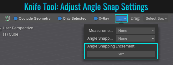
Angle Constraints
It is possible to use the knife tool to cut in constrained angles (in 45° increments). Simply ensure your face(s) is facing the camera directly (either use one of the orthographic views or with the desired surface face(s) selected, press Shift + Numpad 7 to align
selection to the camera) and then press K to activate the knife tool, the press A. When you start cutting, as you move the mouse cursor around the preview knife line will rotate to match the nearest angle snap! This is handy for cutting perfect horizontal / vertical or
45° lines! Pressing A again will toggle between screen-space and local constraints! You can also set the Angle Snapping Increment setting as well!
Snapping
You can snap cut the middle of an edge by either having the snap tool enabled using the Edge Center snap setting, or by simply pressing Shift while cutting an edge!
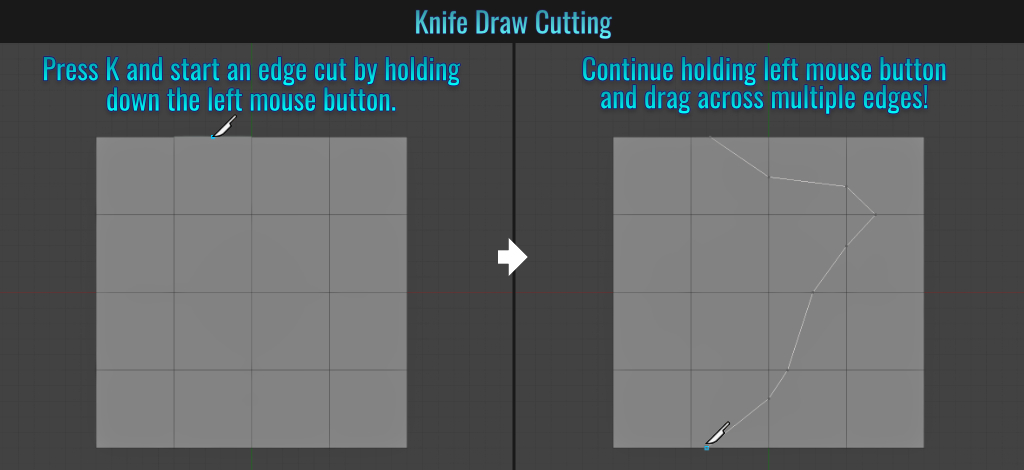
Cut Drawing
Press K and hold down the left mouse button and drag across a mesh with multiple edges on the surface you are cutting. As your cursor crosses an edge, a cut is automatically inserted! Holding Shift while cut drawing will snap to the edges center as mentioned in the
above section.
Undo Cutting
While the cut operation is still active, it is possible undo sequentially from the most recent point by simply pressing Ctrl + Z and then resuming the operation from there!
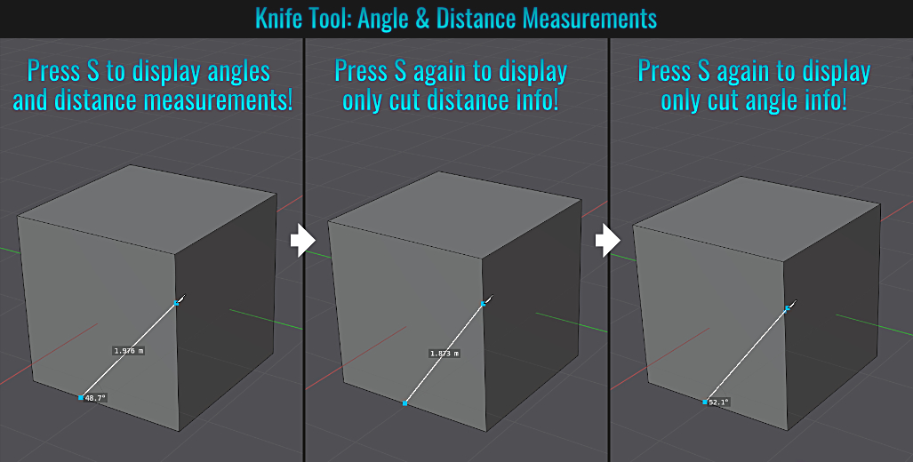
Display Angles & Distance Measurements
Pressing S during a knife cutting operation will display measurements such as the angle of the current cut as well as it's length! S again multiple time while initial angle / distance measurements is active will toggle between displaying only angles and only distances!
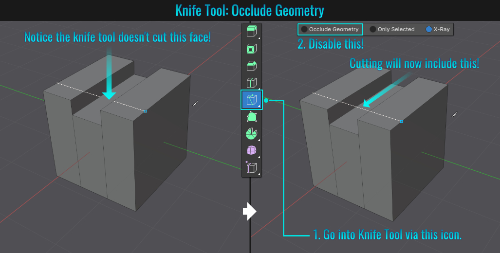
Occlude Geometry
Under certain circumstances, you may notice that some geometry isn't included in the cut operation (as demonstrated in the screenshot below). The solution in these cases is to enter the knife tool mode from the left hand side viewport icons (press T to bring them up if you don't
have these visible). Once in this mode, notice there are some options along the top of the viewport, one of them being Occlude Geometry. By disabling this, the cut should cut through faces that would normally be occluded!
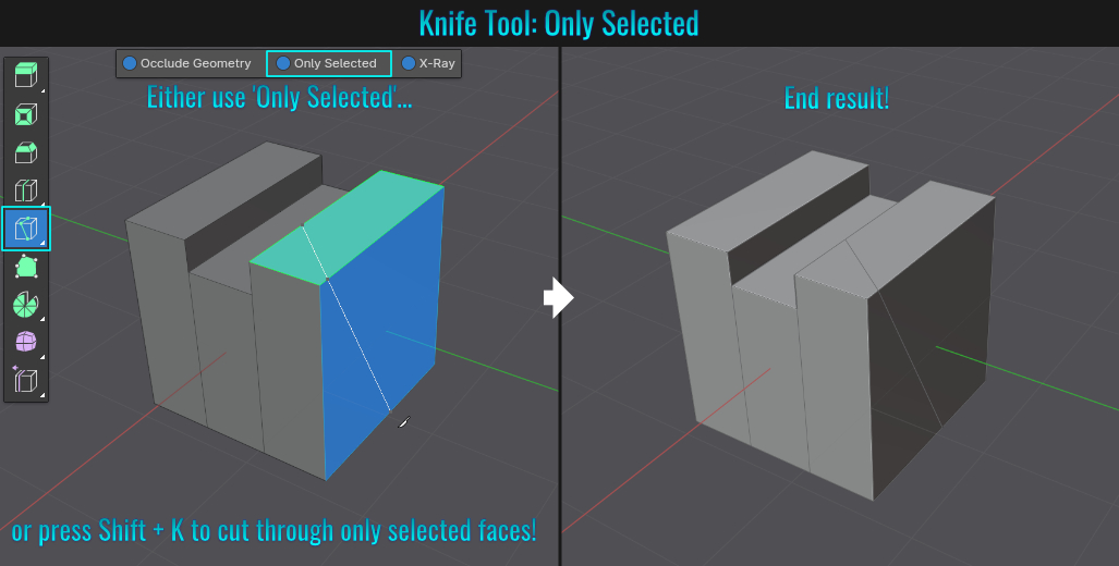
Only Selected
When it comes to cutting through only selected faced, you have two options:
- Go to the knife tool icon and enable Only Selected -or-
- Press Shift + K
- Scale Interface
The default interface can be modified to be enlarged or decreased to your personal preferences. There are two parts to this. One is to adjust the scale to entire global interface while the other enables you to scale individual panels!
Scale Interface Globally
Simply go to Edit > Preferences > Interface and adjust the Resolution Scale value!
Don't forget to save your preferences!
Scale Panels
While hovering over a viewport panel, either press Ctrl and MMB left-click drag -or- Ctrl + Alt and left-click drag to enlarge or shrink it (if no panels are present, press T to bring the left side or N to bring the right side panels).
- Repeat Last Action
Once you execute a feature, you can repeat it by pressing Shift + R. This will save time instead of manually repeating the last feature over and over again. Example: say, select the face of a plane and right-click and choose Subdivide. To keep subdividing, simply use the shortcut!
- Eliminate .Blend1 Backup Saves
By default, when you save a Blender scene, an extra file which is treated as a back up file is also created (it will have the suffix .blend1). This adds unnecessary bloat, especially when committing these extra files to repositories like GIT or Perforce for example.
To eliminate this, simply go to Edit > Preferences and in the Save & Load panel, set the 'Save Versions' value from 1 to 0. Save your preferences if you don't have auto save enabled. From now on, any time you save a Blender scene, no backup files will be created!
- Resetting Colour Values Back To Default (White)
A quick way to reset a colour wheel (or gradient) back to its default setting (white), simply hover your mouse over the wheel (or gradient) and press Backspace. Instant reset!
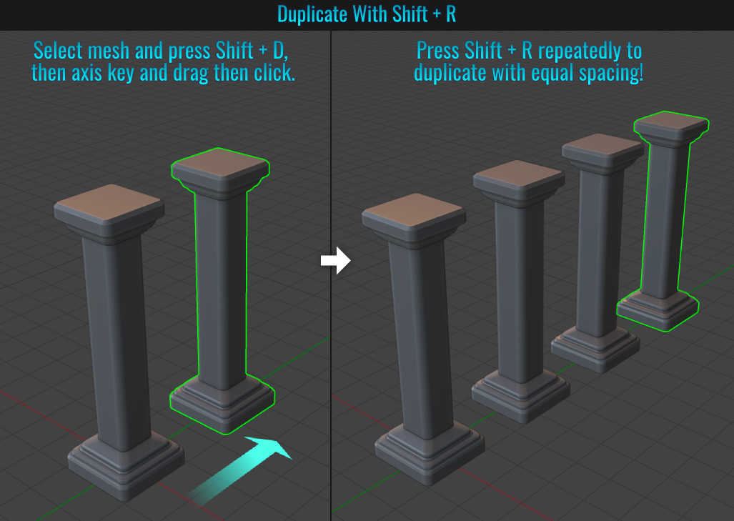
- Duplicating Evenly Spaced Meshes
Sometimes there's no need for using the array modifier for duplicating multiple evenly spacing meshes. Select a mesh and press Shift + D to duplicate it (or Alt + D to instance them - in either case, do not right-click to cancel transforms nor left click to
complete the operation at this point), then press G and then the axis key (X, Y or Z) for the desired axis and move the copy/instance to where you want it and left-click to finalize it.
Finally, press Shift + R
(redo last operation) to constantly duplicate/instantiate the mesh with equal distance between them. This is a fast way of creating things like vents or a row of pillars that repeat for example!
- Quick Ways To Make Stairs
Method 1: Using Bevels
You can create some quick steps using the bevel tool! Take a cube and select a top edge and press Ctrl + B to bevel it and make a wide bevel. With the tool still active, use the mouse wheel to scroll and create enough rounded segments to work with and left-click to finish
the bevel.
With the tool still active, locate and open the bottom left hand side 'Bevel' redo panel in the viewport. Change the profile type to Custom and in the Preset dropdown menu just below, choose Steps! If there are not enough or too many steps,
simply adjust the 'Segments' slider and re-choose the steps preset from the Preset menu!
Method 2: Using Skin Modifier
The idea behind this method is to apply a modifier to a series of vertices. Start with a single vertex selected, and from within an orthographic view (say right side), press E to extrude and place this
newly extruded vertex on an upward slope (you can hold down Ctrl when dragging the mouse after the extrude operation to constrain the second vertex to certain snap angles, like say 45°).
Once the second vertex is placed, select both vertices, right click and choose
Subdivide a few times to add a few more vertices along the edge. Now select all vertices, press X to bring up the Pie Delete menu and choose Only Edges & Faces (this in effect will dissolve all edges/faces, leaving only vertices remaining).
Once again, select all vertices and from within the Modifier panel, choose Skin! You now have some "stairs"!
What's important to note here is that the amount of subdivisions used will determine how large (or small) the individual steps become! This method won't result in
the cleanest geometry, but it still counts as one way of making some quick stairs!
Method 3: Radial Stairs Using Array Modifier
Start by pressing Shift + A and choosing Mesh > Circle and from within the redo panel in the lower left hand corner of the viewport, set the desired Vertices value and ensure that the Fill Type is set to Triangle Fan.
Next, select all the faces and press I to inset them to establish the stairs width. Delete the inner inset faces, then choose an individual face, press Ctrl + I to invert the selection and delete the other faces.
At this point, to add a thickness to the
step, you can either:
- add a Solidify modifier -or-
- select the face and press E to extrude it
Next, in Object Mode, add an Empty object (say Plain Axes for instance). Now select the step and add an Array Modifier. Within this modifier, disable Relative Offset, enable Object Offset and choose the Empty object as
the offset! Adjust the array Count value, then select the Empty object and move its position vertically (Z axis) to adjust the stairs overall height and rotate it (Z axis) to determine how the array fans out!
- Origin Point Placement
In Blender it's possible to relocate a mesh's origin point! Some methods are fast and easy while one in particular (which many teach online and is quite frankly more cumbersome and likely unnecessary) involves the 3d cursor. The following examples will go through some of the options available to you. In all examples, you will need to have a mesh selected. If your mesh origin or 3d cursor is not visible within the 3d viewport, start by simply going to the Overlays menu along the top of the viewport and enable the Origin and 3D Cursor options!

Manual Origin Point Placement
Simply press Ctrl + . (not the period one on the numpad). You'll notice the axis gizmo overlaying the origin. From here, you can press G to move it, R to rotate it or even S to scale it! Additionally,
it will snap to any snap settings you have enabled, giving you the quick flexibility of snapping the origin to whatever you need! Pressing Ctrl + . again exits manual origin placement mode.

Set Origin To Selected (Pie Menu Add-on)
Another simple way is to make a selection and move the origin point directly to it! The first step will require enabling an included free add-on. Go to Edit > Preferences and from within the Add-ons side panel, search for pie and enable Interface: 3D
Viewport Pie Menus! This will affect many menus from pressing the X key for deleting elements to saving (Ctrl + S) and much more (for the better)! Next, with a mesh selected, press Tab to go into Edit Mode and select a component you want
the origin point to snap to. This can be a single selection such as a vertex, edge or face, or it can be a multiple selection of components (in this case, the average center of the selection will be the resulting location). Finally, press Ctrl + Alt + X
(this brings up the dedicated Origin menu - akin to Shift + S bringing up the 3d Cursor Snap menu). Choose the top option called Origin To Selected. Voila! Now your origin point should be located at the selection! Very quick and easy!
No muss and fuss (unlike the next method!)

Set Origin To 3D Cursor
Perhaps the most cumbersome (and common method unfortunately) is the classic "move the origin point to the 3d cursor"! Here is the general workflow. Place the 3d cursor to a specific location by holding Shift and right-click dragging in the 3d viewport (feel free to enable
snapping and snap the cursor to something if need be). If you have enabled the Interface: 3D Viewport Pie Menus add-on mentioned above, you have an additional option to those already available. You can Either:
- Press Ctrl + Alt + X and choose Origin to Cursor from the Origin menu (this is the added modifier option) -or-
- If you don't have this add-on enabled (or are just used to the traditional origin menu instead), go to Object > Set Origin from the Object menu within the 3d viewport top menu and choose Origin to 3D Cursor from there -or-
- Right-click (to bring up the Object contextual menu) and select Set Origin > Origin to 3D Cursor.

If the goal is to set the location of the origin point to the same location as the 3d cursor, which is in turn based on the location of a selection, this method becomes a complete waste of time and is rendered utterly irrelevant given the Set Origin To Selected method!
Of course, there are other origin placement options at your disposal - such as Origin to Geometry, Origin to Center of Mass (Surface) and Origin to Center of Mass (Volume). If you have the aforementioned add-on enabled (highly recommended),
you get access to two extra features that are not included in the traditional Object menu within the 3d viewport top menu:
- Origin to bottom brings the mesh origin point to, well, the bottom of the mesh (useful for meshes like posts, trees, etc...) to ensure quick and easy grounding on say the Z axis for instance!
- Origin to Selected places the mesh origin straight to the selection!
There are many options available here to make life a lot easier with regards to mesh origin point placement!
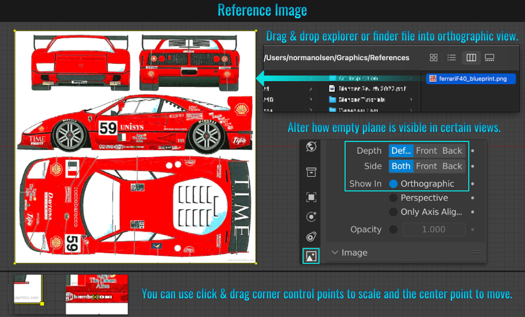
- Reference Images
You can drag and drop an image from Windows Explorer/Finder onto your 3D Viewport (in Object Mode only) to use as reference! This in essence becomes an empty plane object with that image mapped onto it and perfectly sized!
Use the corner control points to uniformly scale the plane while the center cross is used to move it around. Being this is a reference plane, you will not be able to go into Edit Mode with it selected!
It's best to drag and drop into an orthographic view like Front, Top or Right
for example as this operation is view dependant! If you drag and drop this into the perspective view, it will align to the viewport camera and initially look correct, but once you start orbiting, it will need to have its transforms reset!
Finally, you can make them only visible in
orthographic view (meaning that in the perspective view, the empty reference plane will not display)! To do this, simply go to object data properties and deselect the Perspective option within the Show In section!
- Mirror Objects
You can mirror an object (be it a mesh, light, camera among other things) by selecting it and pressing Ctrl + M, then the desired axis key and left-clicking to finalize the mirror operation!
Note: Mirrored geometry will result in invert face normals,
so be ready to correct that -Shift + N!
- Checker Deselect
This feature deselects every other face on the mesh. Fluted pillars benefit from this by quickly adding insets and inner extrudes, or perhaps adding geometric details or a different material to chess or checkerboards for example. To do this, simply select all the faces involved and from the top viewport menu, choose Select > Checker Deselect. Within the Checker Deselect redo panel on the bottom left of the 3d viewport, adjust the Deselected or Selected sliders to achieve every nth selection (for cylinders, loop select all the side faces as opposed to box selecting them).
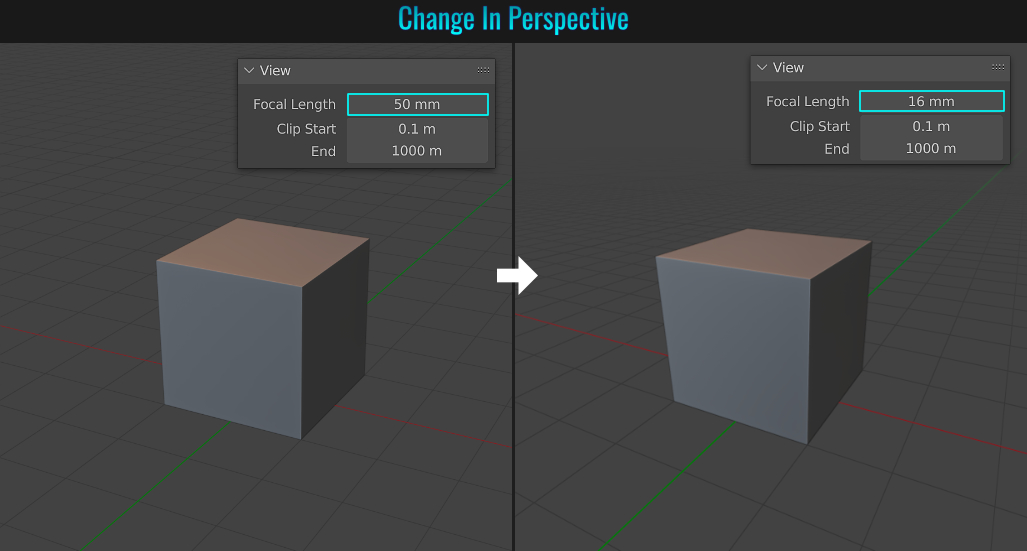
In the event you feel that the default perspective view is not to your liking, it's pretty easy to change it. Simply press N in the viewport to bring up the right hand side panels and select the View panel. From there, it's just a matter of sliding the Focal Length variable to change how the perspective is calculated. The default is a focal length of 50mm (which is usually good enough for most people).
- Random Selections
It's simple to be able to randomly select meshes, or faces (or edges or vertices) on a mesh. Just go into Edit Mode, and with a mesh selected, go to Select > Select Random from the viewport menu. A Select Random redo panel will appear on the lower left hand side of the view
port.
Here, you can interactively adjust the Ratio and/or Random Seed values to achieve different random selections. By default, the Action mode is set to Select, which of course means it will select. But you can change this setting to
Deselect as well!
- Redo Panel
Fun fact: Pressing F9 will bring up a popup displaying the last operation you performed. So for example, let's say you just added a cylinder and left-clicked to end the operation. You can use F9 to bring back the cylinder redo panel (in the form of a re-positional popup) and readjust its settings (like segment count). Could come in very handy from time to time!
- Loop Cut Tool
Simply hover your mouse cursor over any edge and then press Ctrl + R to invoke the loop cut tool. At this point, you get a new central edge loop, but with this tool still live, so you have some options here... if you scroll with your
mouse wheel, you can increase (or decrease) the mount of evenly spaced additional edge loops.
Left-clicking finalizes the amount of edge loops and now allows you to move your mouse or tablet pen around to slide and place the edge loop(s) where you want it (right-clicking
auto centers these edge loops and exits the loop cut functionality while left clicking stamps the edge loops in place and exits the tool). However, one cool additional thing during sliding / placing phase is that if you hit E, the loops will confine to the lower edge loop shape while
pressing F will confine to upper one!
- Rip & Rip Fill
Rip
In Blender, the term rip simply means breaking vertex connections. Simply select vertex / vertices or edge(s) and press V! Now the selection will no longer be connected, allowing you to move them freely. As a bonus, this also applies in the UV Editor
(only applies to rip, not rip fill!)
Rip Fill
Blender also offers the ability to rip but cap the hole that would normally be left behind! To do this, simply press Alt + V!
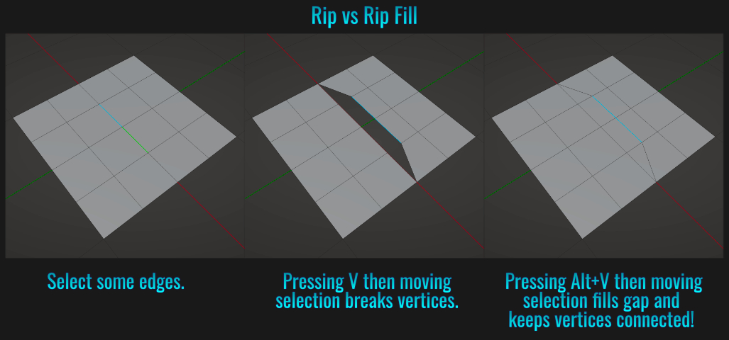
Side Note: The rip fill operation direction will determine which side of the selected edges the mouse cursor is hovering over! Much like edge ring selections when using Emulate 3 button mouse, the cursor location matters!
• Bonus! While not considered a rip fill, you can select a vertex and press Alt + D to add a connected vertex!
- Extrude Features
Click Extruding
You can extrude a selection by holding Ctrl and right clicking! The selection will extrude to the mouse cursor! This can come in handy when say manually modeling a tree. Selecting faces on a trunk and Ctrl right clicking off the trunk will produce the starting point of a
branch. From there, simply scale the branch tip down a bit, then repeat the process to quickly finish the branch off!
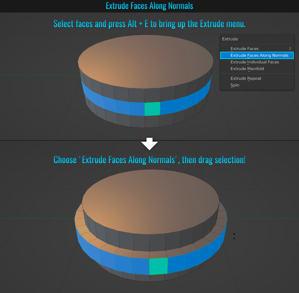
Extrude Faces Along Normals
It's sometimes useful to extrude faces along their normals! The process is simple. Make a selection of faces and press Alt + E to invoke the extrude menu. From here, simply choose Extrude Along Face Normals and drag to create the extrusion process!
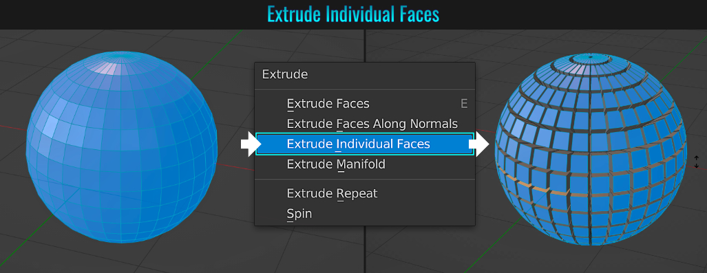
Extrude Individual Faces
This extrudes all faces individually along their face normals.
- Shrink / Fatten
Sometimes you might want to slide a vertex or face along its normals. This is as easy as making the selection and pressing Alt + S and dragging the mouse! After left-clicking to finalize the operation, a Shrink/Flatten redo panel appears in the lower left hand corner of the viewport with options like adjusting the offset or enabling offset even (which provides a more uniform thickness as well as proportional editing.
- Separate By Loose Parts
A feature that might be overlooked is the ability to separate a mesh into loose parts. This comes in handy when you need to break a joined mesh into individual meshes, and only works with disconnected fragments (no vertices between parts welded together).
To do this, simply select the
main mesh in question, enter Edit Mode, choose Face Select and tap A twice to select all faces. Finally, press P to bring up the Separate panel and choose By Loose Parts. Now, all disconnected mesh fragments will be their
own individual meshes!
- Extra Primitives (Like Capsule)
Did you know that there are a few extra primitives (like the capsule) in Blender? To begin, ensure that the Add Mesh: Extra Objects add-on is installed. Then simply press Shift + A and from the resulting Add menu, choose Mesh > Round Cube. A rounded cube appears in the scene. Next, locate the Add Round Cube redo panel on the lower left hand corner of the 3d viewport, open it and from the Operator Presets drop down, you'll notice there are a few new primitives to choose from!
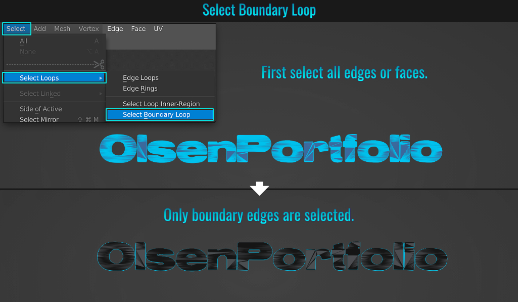
- Select Boundary Loop
Ever need to select the open edges of a mesh? There is a fast way to selecting all them by select all edges or faces on the mesh, then in the viewport top menu, choose Select > Select Loops > Select Boundary Loop! Voila! All outer open boundary edges selected, just like that!
- Quick Dissolve
When cleaning up meshes and you want to dissolve (instead of delete) sub selections, you can press X and choose Dissolve (insert sub-selection here: Vertices / Edges / Faces). But an even quicker way is to simply press Ctrl + X. This is faster than bringing up the delete/dissolve menu!
- Delete Without Confirmation
When deleting a mesh in Object Mode by pressing X, you are always greeted with a small confirmation popup verifying if you want to delete it. This can become annoying and
cumbersome over time! You have two options to bypass the confirmation process altogether. Either:
- press Delete (beneath the insert key) -or-
- go into your preferences and from within the keymap panel, search for delete. Scroll down to the Object Mode version using the X keyboard shortcut. Open this key map panel and notice that by default, the radial button for Confirm is enabled. Simply disable this and save your preferences! From now on, when in Object Mode, there will no longer be a confirmation popup every time you use the X key to delete something!
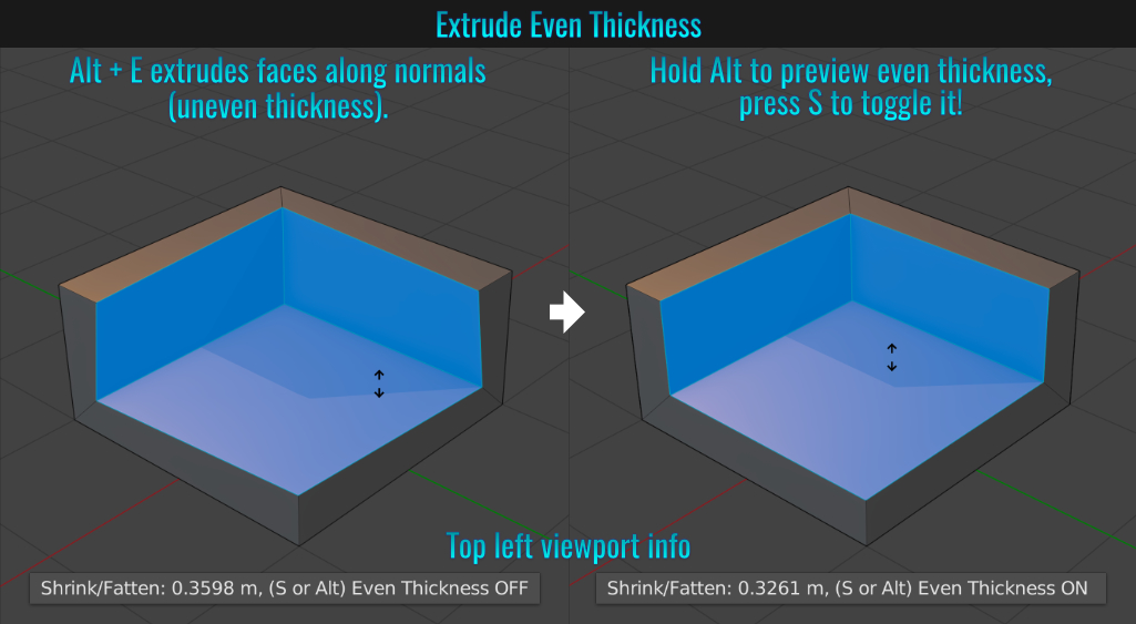
- Extrude Even Thickness
When wanting to apply a thickness to some non-manifold faces, you have two options:
- Apply a Solidify modifier and enable Even Thickness - or -
- With faces selected, press Alt + E to bring up the Extrude popup. Choose Extrude Faces Along Normals. At this point (with the tool still active), the extrude will look uneven. Holding down Alt will preview the even thickness while pressing S will toggle it on or off!
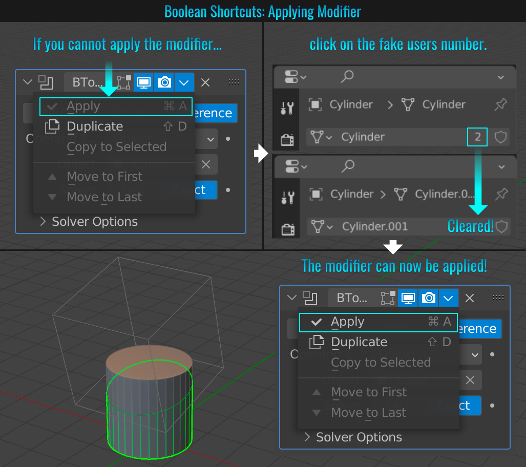
- Quick Boolean Shortcuts
Here is a fast way for creating booleans: Select the "source" mesh (in this case, the cube), then press Shift + left click the "target" mesh - in this case the cylinder. Now do one of the following:
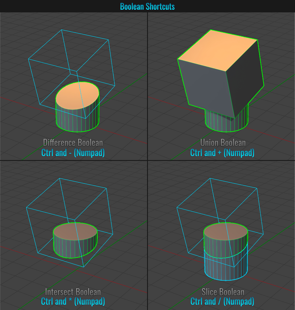
The final result will in fact mean a boolean modifier with the chosen operation will be added to the target mesh! If the Apply option from the boolean modifier dropdown is greyed out (this is particularly common with slice operations as two meshes share the same cutter), simply ensure that the target mesh is selected, and from within the Object Data Properties panel, simply click on the number representing the number of fake users: This will remove the users and from here, you should be able to apply the boolean modifier!
- Correcting Missing Faces On Exported FBX File
There might be a time that you need to work with an existing imported fbx file (no working scene found, or starting with a mesh purchased online) in preparation for exporting into Unity, and the end result is an fbx mesh with missing faces! Here are the most common issues and their solutions to
this problem:
Flipped Normals
The most likely culprit is that face normals are inverted. Ensure that the mesh normals are facing the right way (from within the top viewport menu, choose Mesh > Normals > Recalculate Outside - or Shift + N).
Improper Materials
If the above solution is not resolving the issue. then it probably has to do with problematic materials. From within the top frame of the Outliner, click on the Display Mode icon button (to the right of Editor Type). When this drop down opens up,
choose Blender File, and from here, open up the Materials section. Start by eliminating one material at a time between exports to find the offending material. it might be a single one or a combination of multiple materials that is causing the problem.
Select and remove the offending materials - it might be a single one that is causing the problem (you might need to eliminate one at a time between exports to find the problematic material).
- Vertex Grouping
Vertex groups is a great feature that allows us to "save selections" if you will. This becomes particularly powerful when dealing with certain modifiers for instance (only affecting certain vertices)! Perhaps you need to create a group to be able to apply vertex paint to, or you need to revisit a
selection to tweak its thickness, or position, or use them in a modifier, etc... The list of reasons are probably plentiful!
Vertex Group Setup
Start by selecting the vertices / faces you want to group together. Do one of the following:
- Press Ctrl + G and choose Assign To New Group from the Vertex Groups popup (this is the quicker / easier way) - or -
- Within the Object Data Properties panel, create a new vertex group by clicking on the + button within the right hand side of the vertex group panel. This will create a default group name called Group. Next, click on the Assign button. Now, any vertices / faces are now assigned to this group.
Either way, it's a good practice to give the vertex group a more meaningful name!
Modifying Vertex Groups
Once a vertex group is set, it's possible to add / remove vertices from said group!
- Adding to group: You can add by making a selection, and with the current group selected, simply click 'Assign' again. This will add the current selection to the complete group selection.
- Removing from group: If there is any vertices / faces you don't want to include, deselect everything, then select only those you don't want to be included in the currently selected group and press 'Remove'.
- Selecting and Deselecting: 'Select' will select any selections assigned to the currently highlighted group while 'Deselect' will deselect the group's assigned selection.
You can create many vertex groups, and even have some groups share some selections. Vertex groups is a powerful way to access the selections you need to make any necessary changes quick and painless!
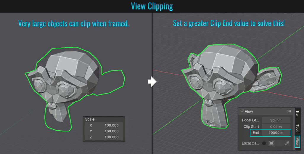
When dealing with very large meshes, often times they will be clipped when framed within the viewport. The remedy is quite easy! Press N to bring up the viewport right hand tab options and from the View tab, simply increase the Clip End value by a large enough value (like adding a zero) and voila! Problem solved!
- Knife Project
The Knife Project tool allows a mesh or curve object to be projected and cut into a background mesh (if the background mesh is not flat/co-planar), you might want to have enough face subdivisions to give enough resolution to work with). The process is simple.
- First select the mesh that you want to receive the cut and go into Edit Mode. Next, from within the outliner, Ctrl + click on a non-manifold mesh that will act as the "cookie cutter". In this case, a mesh with open edges / borders.
- From within the top viewport menu, choose Mesh > Knife Project. Note: The viewport camera will determine the angle of the projection (think project from view), so it's best to go into an orthographic view for this.
- The resulting projected faces are automatically selected. From here, the creative possibilities are plentiful! If you wish to have the knife project go through the entire mesh, simply enable Cut Through in the Knife Project redo panel in the lower left hand side during the project operation! View the document for more details.
- Adjusting View Through Camera / Light
- Select a camera or light.
- Press N to bring up the right-hand side panel and go into the View tab.
- Enable the Camera To View option from within the View Lock section.
- Press Ctrl + Numpad 0 to jump the view into the first person perspective of selected camera or light.
- From here, navigate in the 3d view to reorientate camera or light, then press Numpad 0 to exit back into normal 3d viewport view.
- Quick Favorites
A good way to access your most frequently used features is to add them to your quick favorites! Most items in drop down menus and panels allow you to right-click on them and chooseAdd to Quick Favorites. When you press Q, you can see all the features you added
for quick and easy access!
But this is not just limited to the 3d viewport! There are multiple contextual Quick Favorites (same shortcut) in other areas like the UV Editor and Shader Editor for instance! So if you frequently use certain nodes
(like Ambient Occlusion or Color Ramp for instance), the procedure for adding them to the favorites list is the exact same! This allows you to store a series of frequently used nodes so you don't have to keep searching and applying them the traditional way! Make sure to set
Quick Favorites in every area relevant to your workflow to give you the most used functionality literally at your fingertips!
- Popular Pie / Panel Menu Shortcuts
Here is a list of some of the more commonly used pie / panel menus, their shortcuts and menu item lists they invoke:
- Pie Shading - Shortcut: Z
- Solid, Wireframe, Shade Smooth, Shade Flat, Rendered, Material Preview
- Solid, Wireframe, Shade Smooth, Shade Flat, Rendered, Material Preview
- Snap - Shortcut: Shift + S
- Selection to Cursor, Selection to Active, Selection to Grid, Cursor to Active, Cursor to Selected, Cursor to World Origin, Cursor to Grid, Selection to Cursor
- Selection to Cursor, Selection to Active, Selection to Grid, Cursor to Active, Cursor to Selected, Cursor to World Origin, Cursor to Grid, Selection to Cursor
- Snap To - Shortcut: Ctrl + Shift + Tab
- Brings up entire Snap To popup panel
- Brings up entire Snap To popup panel
- Pie Proportional Obj - Shortcut: Shift + O
- Proportional On/Off, Inverse Square, Sphere, More, Linear, Sharp, Smooth, Root
- Proportional On/Off, Inverse Square, Sphere, More, Linear, Sharp, Smooth, Root
- Pivot Point - Shortcut: .
- Median Point, Only Locations, 3D Cursor, Individual Origins, Bounding Box Center, Active Element
- Median Point, Only Locations, 3D Cursor, Individual Origins, Bounding Box Center, Active Element
- Orientation - Shortcut: ,
- Gimbal, Cursor, Local, Normal, Global, View
- Gimbal, Cursor, Local, Normal, Global, View
- View - Shortcut: ~ (Tilde Key)
- Top, Back, Right, View Selected, Bottom, View Camera, Left, Front
- Top, Back, Right, View Selected, Bottom, View Camera, Left, Front
- Mode Switch - Shortcut: Ctrl + Tab (with an object selected)
- Object/Edit Mode, Vertex Paint, Texture Paint, Edit Modes, Weight Paint, Sculpt
- Object/Edit Mode, Vertex Paint, Texture Paint, Edit Modes, Weight Paint, Sculpt
- Origin Menu - Shortcut: Ctrl + Alt + X
- Origin to Selection, Origin to Geometry, Origin to Cursor, Origin to Bottom, Origin to Center of Mass, Geometry to Origin
- Origin to Selection, Origin to Geometry, Origin to Cursor, Origin to Bottom, Origin to Center of Mass, Geometry to Origin
- Save Defaults - Shortcut: Ctrl + U
- Save Startup File, Save User Preferences, Load Factory Preferences, Revert to Saved Preferences, Load Factory Settings, Autosave Preferences
- Save Startup File, Save User Preferences, Load Factory Preferences, Revert to Saved Preferences, Load Factory Settings, Autosave Preferences
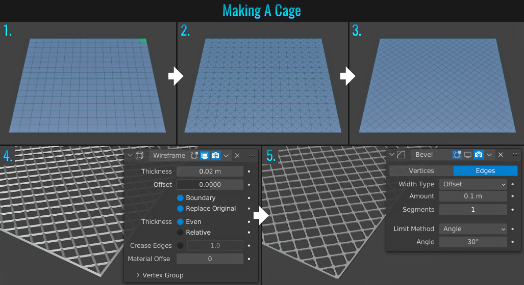
- Quick Way To Make A Cage
- Create a plane, select all faces, right-click and choose Subdivide and press Shift + R(redo last action) a few times to give it enough subdivisions (not too many though).
- With all faces still selected, right-click and choose Poke. This will result in a central vertex for each face.
- Now right-click again and choose Tris to Quads (or press Alt + J). This will result in a grid pattern that is rotated 45°!
- Go into Object Mode and add a Wireframe modifier to it. Play with the Thickness option to achieve the desired look. You can even enable the Boundary option to auto cap the open edges!
- Feel free to further dress the cage up by applying a Bevel modifier and playing with the Amount and Segment count to give it a more stylized look!
- Exporting UV Layouts
In Blender, It's possible to export mesh UVs. This be useful when doing paint overs in Photoshop for example (as a hand painted texture) and you need to know how the mesh UVs are layout out. You can put the exported UV images into your PSD file and use it as reference!
- Simply go to UV > Export UV Layout from within the top UV Editor menu.
- From within the save popup, notice that there is a set of options within the top right hand corner. This is where you can set the type of file, the file size, etc... If you enable All UVs, this will result in all UVs being exported (no need to manually select all UVs for this to work).
- The end result is the entire set of UVs exported into the file type of your choosing!
The fun doesn't stop there however! Did you know that you can export only selected UV islands instead of the entire thing? Simply ensure that Modified is enabled instead of All UVs when intending to export only what you need! This can prove useful when needing to
paint over only parts of the mesh texture, serving as a way to isolate where to paint by treating it as a mask!
- Creating A Custom Orientation
In Blender, there is a set of custom orientations within the Transform Orientation drop down from within the top menu just above the 3d viewport. The default orientations include:Global, Local, Normal, Gimbal, View and
Cursor.
Chances are, one of these will satisfy your transform needs. However, there might be some situations where they don't work and as a result, creating a custom orientation based on a selection is the solution! Let's look at a simple example to illustrate this.
Suppose that by accident, a trapezoid hole in the wall (to accommodate a window frame) had a misplaced vertex like so:
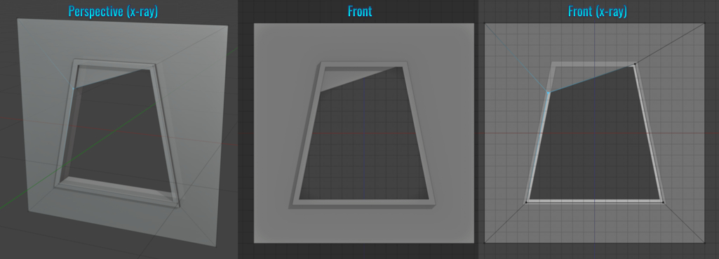
The solution here would be to create a custom orientation!
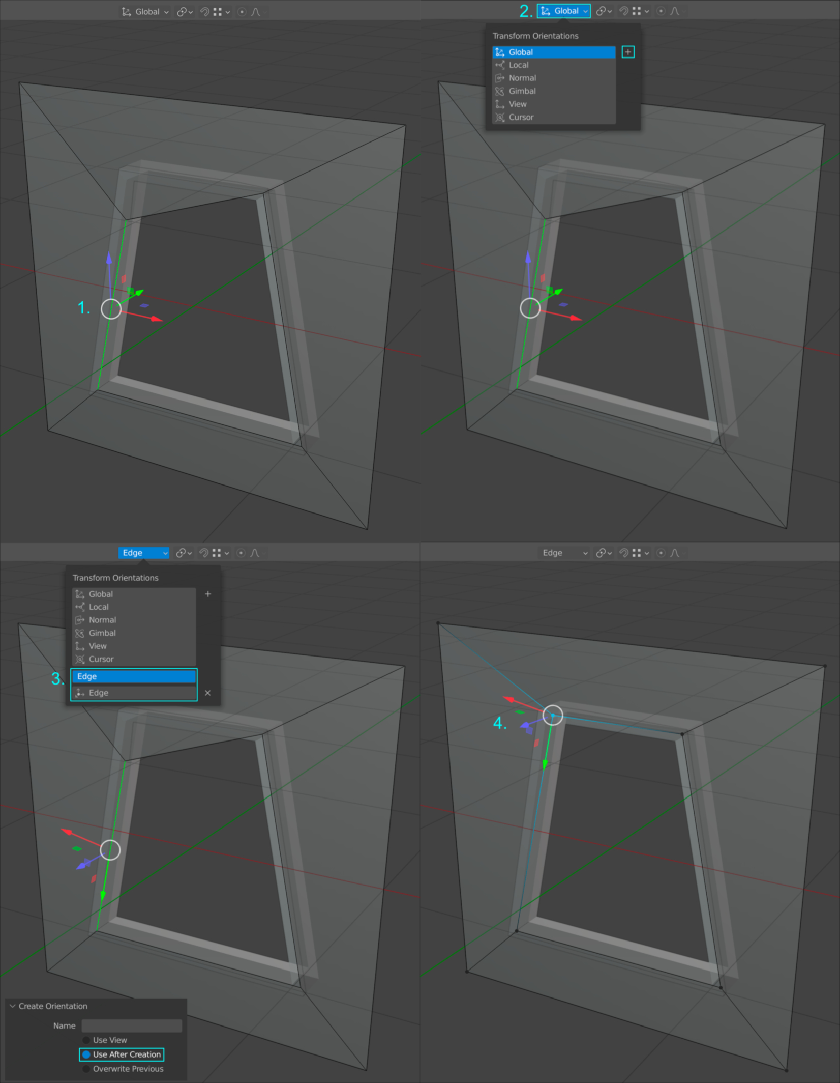
- Select the edge or vertices that involve the offending vertex.
- Locate and click on the Transformation Orientation drop down located within the top viewport menu. Click on the side + button to create a new orientation.
- A new 'Edge' category is created below the default list! Within the panel in the lower left hand corner of the viewport, the option for Use After Creation should be enabled by default! Notice that the transform gizmo is now orientated to match the selection!
- Now, when transforming the offending vertex, it will follow the vector of the edge (or selected vertices) it belongs to, enabling you to easily slide it into the correct position. Once you are finished with this orientation, you can easily delete it by clicking on the X button next it!
There are many other possibilities beyond this example that can make use of custom orientations! When the need arises, rest comfortably knowing
that Blender allows you create any orientation you need! As a bonus, there is another (and simpler way) to solving this issue. Please see tip #72!
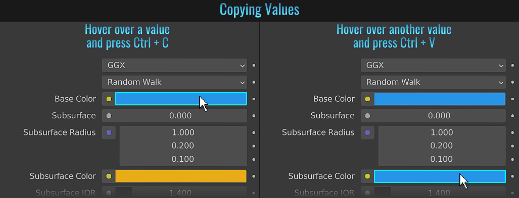
- Copying Values
When it comes to copying values from one place to another (in this example, colour swatches), instead of opening up the colour panel and copying the values, then opening another colour panel to paste them, you can simply hover your mouse cursor over the first colour and press Ctrl + C, then hover over the target colour and press Ctrl + V! This technique applies to pretty much any values you'll find scattered across Blender. It's not limited to colour info!
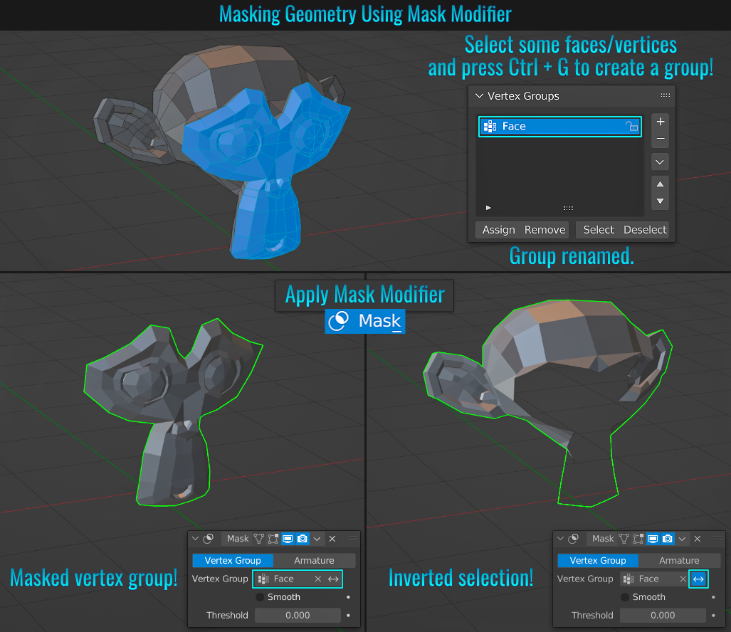
- Mask Modifier
You can nondestructively mask portions of your mesh! Simply select some mesh faces / vertices you wish to mask and create a vertex group from them (see tip Vertex Grouping). Then add a Mask modifier. Choose the vertex group you created for the Vertex Group field. Now only the masked polygons should be visible! You can toggle between the mask and the rest of the mesh by pressing invert button!
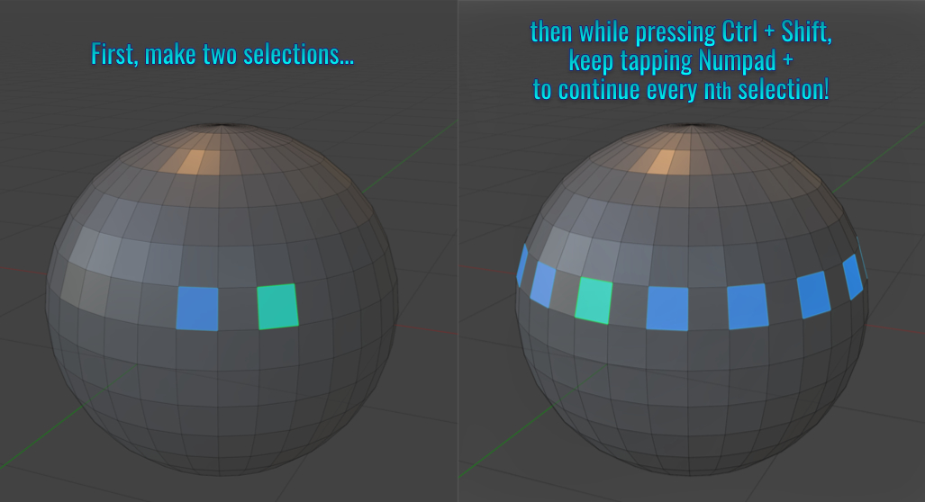
- Select Every nth Element
When it comes to making repeated offset selections, simply select the first and second element (vertices, edges or faces) on a mesh with the desired spacing in-between, then while pressing Ctrl + Shift, press Numpad + as many times as needed to replicate the nth selection (mesh topology will determine how reliable / useful this feature is)! Pressing Ctrl + Shift, press Numpad - subtracts from the selection pattern instead!
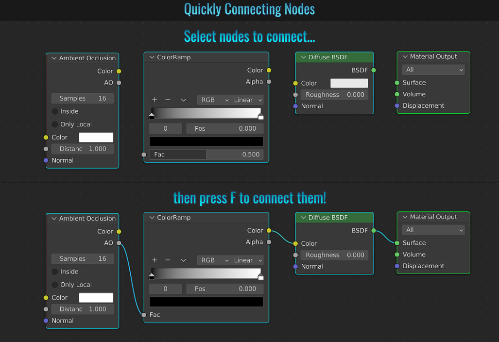
- Quickly Connect Nodes
When it comes to connecting nodes, nothing is faster than simply selecting the ones in question you'd like to connect and pressing F. One thing to note about this method is that only primary "Default" inputs and outputs will be connected! This will not connect an output from one node to say, a FAC input of another for example.
- Render Region
When dealing with complex, heavy scenes using the Cycles Rendering Engine with the viewport mode set to Rendered, it can become time consuming to tweak something (like say lighting for instance) and have Blender recalculate everything. Luckily, there's a feature called
Render Region that allows calculations within a designated rectangular region.
To do this, simply press Ctrl + B and left-click drag out a rectangular region. This will be represented onscreen as a rectangular dash bordered region. From here on, only
the region will be calculated. Placing the mouse cursor in the center will give you control to move the entire region around while placing it on the corners or edges will allow you to change its dimensions! To remove the region, simply press Ctrl + Alt+ B.
This doesn't just apply to viewport rendering though! Using a camera, the rendered region will only render out what the camera sees! By default, any space that isn't filled with geometry or a background will be just alpha space. If you don't want any empty space outside of the render to
be included, simply go the Output properties tab and from with the Format panel, simply enable the Crop to Render Region feature!
- Making A Camera Active
There's a few ways to make a camera among other cameras the active one. You can either:
- Select a camera from either the 3d viewport or from within the outliner and press Ctrl + Numpad 0 -or-
- From within the Scene Properties tab, choose your camera via the Camera drop-down menu.
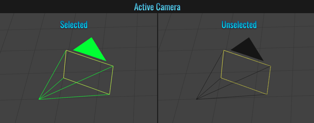
It is important to note that every camera has a wire frame triangle above the rectangle which represents its FOV. When a camera is active (not to be confused with whether it is selected or not), this triangle is filled solid! Otherwise, the triangle is simply an outline (thus the camera is
not active). The active camera will be used to calculate the final render - regardless to whether it is selected or not!
- Don't Load Someone's Layout In A Blender File
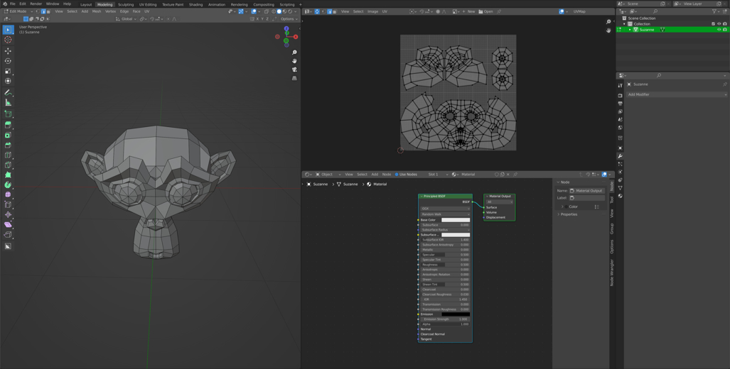
Ever open a Blender file only to be greeted with a custom layout that you feel is unwanted? Luckily, Blender has your back! Let's look at an example and see how to load it without the saved layout in the file!
Here is an example of a saved file with the modelling
workspace's layout reconfigured.
Start by creating a new scene by either going to File > New or pressing Ctrl + N (or by loading a different scene, as you can't try and reload the same scene using this technique). Once the new scene is up, load the file in question via File > Open (don't load via Open Recent, as this bypasses the file load window!) Once this load window is open, locate the Options (gear) icon in the very top right hand corner and uncheck the Load UI option!
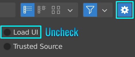
Now select the file in question and load it. Notice that your UI layout remains intact instead of the version saved within the scene! This is much quicker and easier than trying to shift/eliminate layout windows to bring the UI back to what you use!
Want to make this behavior permanent? Simply go to Edit > Preferences and from within the Save & Load panel, simply uncheck Load UI and save your preferences!

- 3D Viewport Transparencies
Displaying transparencies within the 3d viewport isn't straight forward, nor is it terribly difficult to achieve! Let's examine two different types. One using a material to make the entire mesh translucent and the other displaying a texture containing alpha information, both of which are viewed in
the Material Preview viewport mode (which makes use of Eevee and by default doesn't display transparency).
Material Transparency
- With the mesh selected, create a new material.
- Within the Setting section, set the Blend Mode to Alpha Blend.
- In the Shader Editor, Add a Transparent BSDF as well as a Mix Shader node. Connect the outputs of both the Principled and Transparency BSDF nodes into the Mixed Shader inputs (see screenshot) and plug the output from the Mixed Shader to the Surface of the Material Output node.
- Adjust the Alpha setting within the Principled BSDF node to achieve the desired opacity of the material (and thus, the mesh in question).
Texture Alpha Transparency
- With the mesh selected, create a new material.
- Within the Setting section, set the Blend Mode to Alpha Blend.
- In the Shader Editor, add the following nodes: Transparent BSDF, invert, image texture and Mix Shader. Connect the image texture node to the Principled BSDF 'Base Color' input and choose a texture that has alpha information in it. Connect the outputs of both the Principled and Transparency BSDF nodes into the Mixed Shader inputs (see screenshot). Connect the Alpha output from the image texture node to the 'Color' input in the invert node and plug the invert into the FAC input of the Mixed Shader node, of which connects into the Material Output Node. Now the alpha texture should display properly within the 3d viewport.
Be aware that you have a few choices in the alpha blend modes. Setting it to Alpha Clip will result in solid opaque or pure transparent pixels while Alpha Blend will give smooth, anti-aliased translucent pixels.
- Sliding vertex beyond edge
From time to time you may find the need to slide a vertex beyond the edge it is connected to. By default, after selecting a vertex and pressing G G, the vertex will slide along either of its connecting edges. But if you wanted to continue sliding the vertex beyond an edge, simply press C to disable clamping and continue dragging the vertex past the corner point!
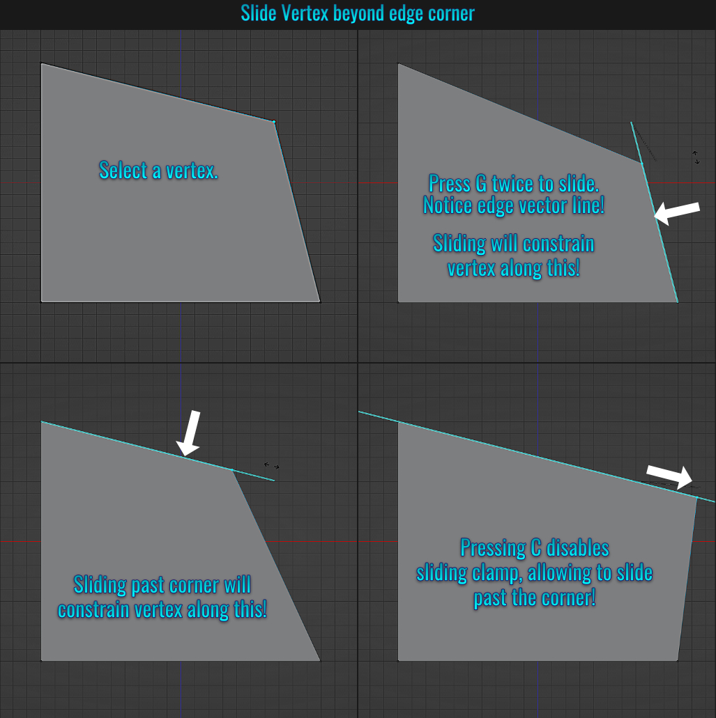
Alternatively, after pressing G G, you can hold down Alt and drag the vertex beyond its constrained edges. It's worth noting though that this will only work if you do not have Emulate 3 Button Mouse enabled in your preferences!
- Circular Array Methods
Blender provides a wide variety of methods for using a radial array on a mesh. Let's examine some different possibilities available at our disposal!
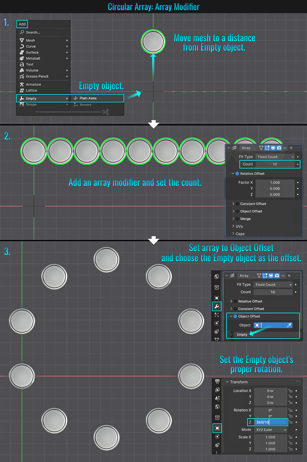
Method 1: Array Modifier & Empty Object
- The first step is to add an Empty Object by pressing A and choosing from the Empty category to your scene with the mesh you wish to make a radial array from. Position your mesh at the desired distance from the Empty object (this will dictate the radial radius).
- Next, add an Array Modifier to your mesh and set the Count value (in this example, 10). You can always readjust this afterwards.
- Finally, disable the Relative Offset and enable the Object Offset instead. Open up the Object Offset panel and from within the Object field, choose the Empty object (or select the eyedropper and manually click on the Empty object from within the viewport). Select the Empty object and rotate it in the appropriate axis by the appropriate amount (this can be entered as an equation that can be something like 360/10 in say the z-axis field - this would represent the total degrees in a circle divided by the amount of mesh copies used). Voila!
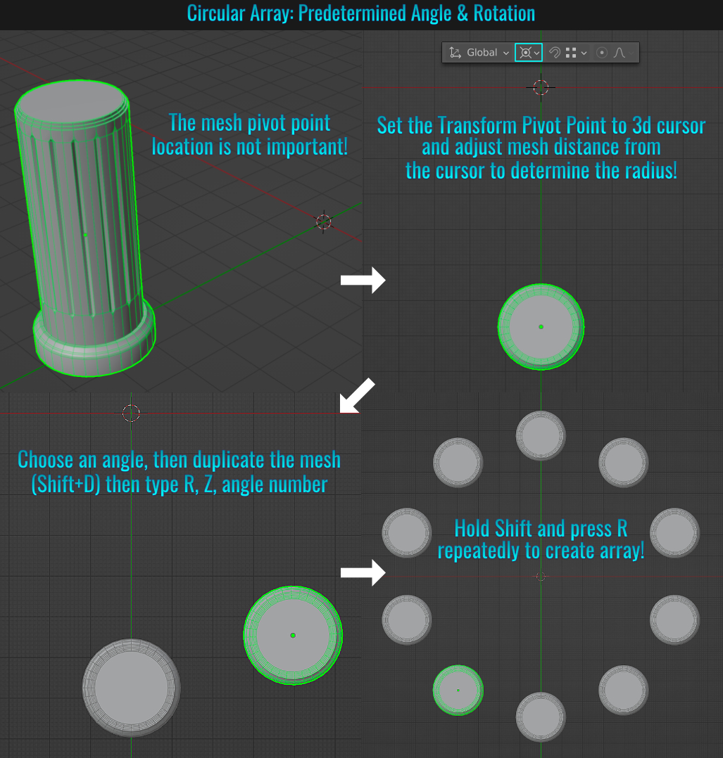
Method 2: Angle & Rotation
First ensure that the Transform Pivot Point is set to 3D Cursor. Place your object the distance you want from the 3d cursor to establish the radius. Next, determine how many copies you want in the circular array (example: 10). So dividing 360° / 10 = 36°.
Duplicate the mesh by pressing Shift + D(or Alt + D if you want to instantiate it), and without left-clicking, type R then Z then 36 and hit Enter. Finally, hold Shift and press R as many times as needed
to complete the circular array!
Method 3: Using Extrude Spin
Using the same pillar example from above, ensure that the mesh's pivot point is set to the 3d cursor's location (this can be done via Object > Set Origin > Origin to 3d Cursor). Select all verts, edges or faces on your mesh and press Alt
+ E (to bring up the Extrude menu) and then press S (for Spin). Voila! Instant radial array! Use the Spin operator panel to adjust the number of meshes within the array!
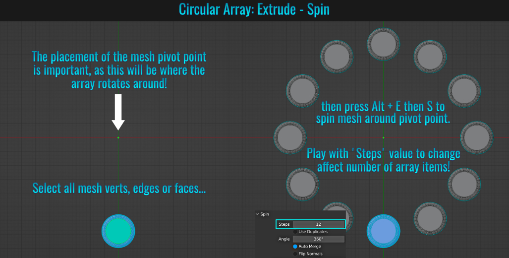
Side Note: This array operation is viewport dependant! While you can get creative, interesting results using a perspective view, it's best to use an orthographic view for this!
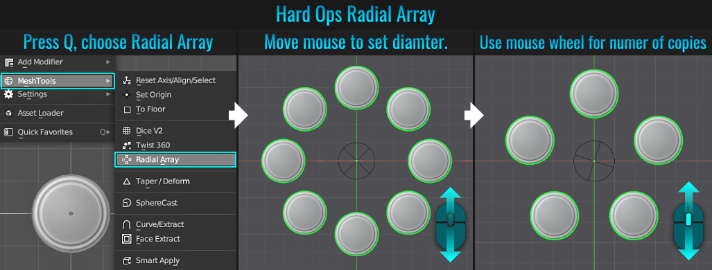
Method 4: Using HardOps Add-On
If you have the paid HardOps add-on installed, you can simply select the mesh you wish to create an array from, press Q
to bring up the HardOps menu and choose Mesh Tools > Radial Array. Use your mouse movement to create the array's diameter, and the mouse wheel to increase/decrease the amount of copies within the array!
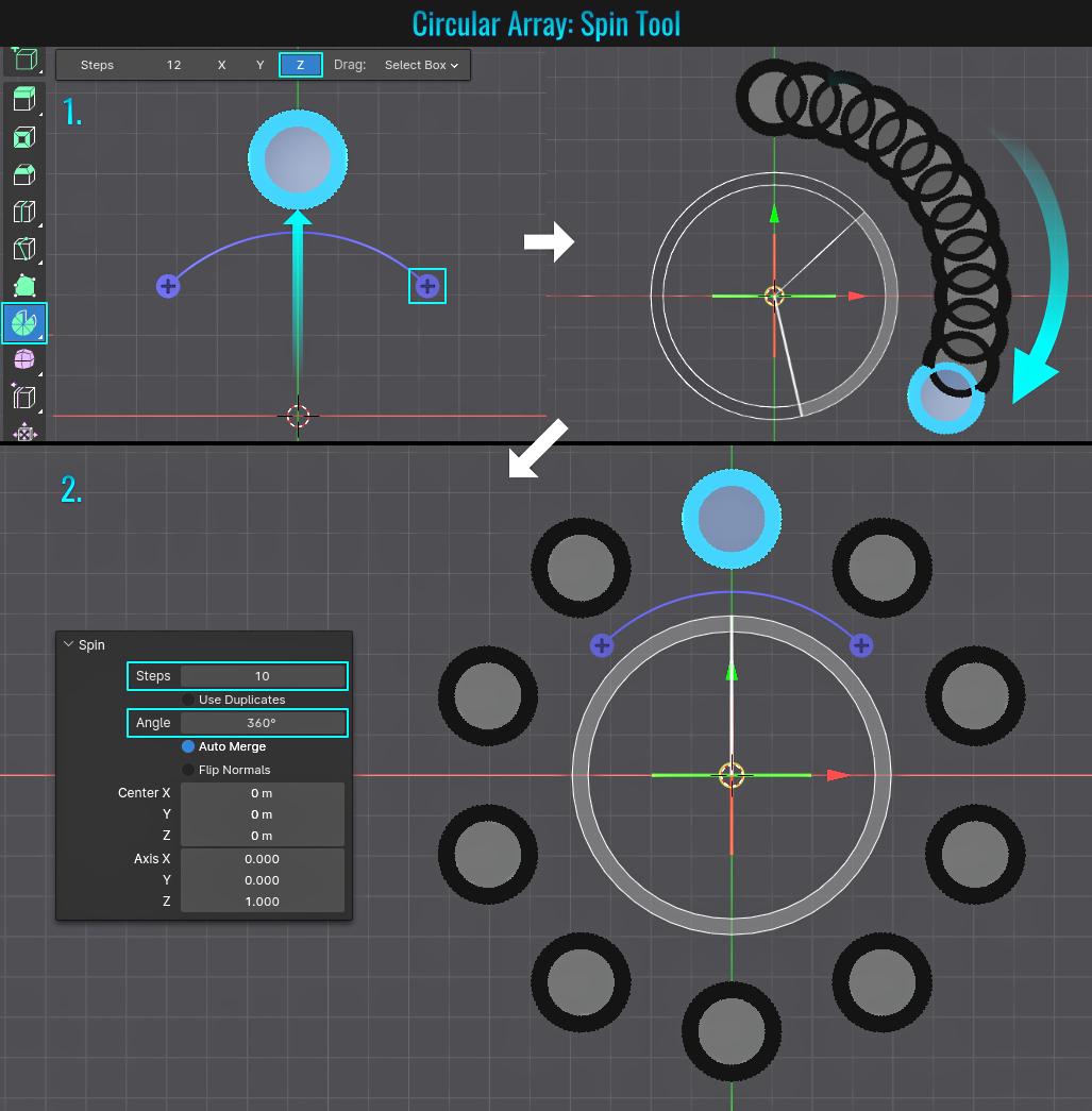
Method 5: Spin Tool
This method simply makes use of the location of the 3d cursor as well as the use of the Spin tool!
- Position the mesh you wish to make a radial array with to the desired distance from the 3d cursor. Go into Edit mode and regardless of which component selection mode you are in, select all of the mesh's elements (you can quickly do this by pressing A to bring up the Pie Selections Edit Mode menu and choose Select All Toggle or press 8). Finally, if the left hand side viewport side menu isn't open, press T to invoke it and choose the Spin tool. After ensuring the proper axis is selected (top left hand side within the viewport) Click and drag one of the spin tool gizmo arch end points to initiate the radial array.
- Finally, in the Spin panel in the lower left hand side of the viewport you can set the overall Angle (which for a full circle would be 360°) and Steps (which is basically sets how many copies will be used)!
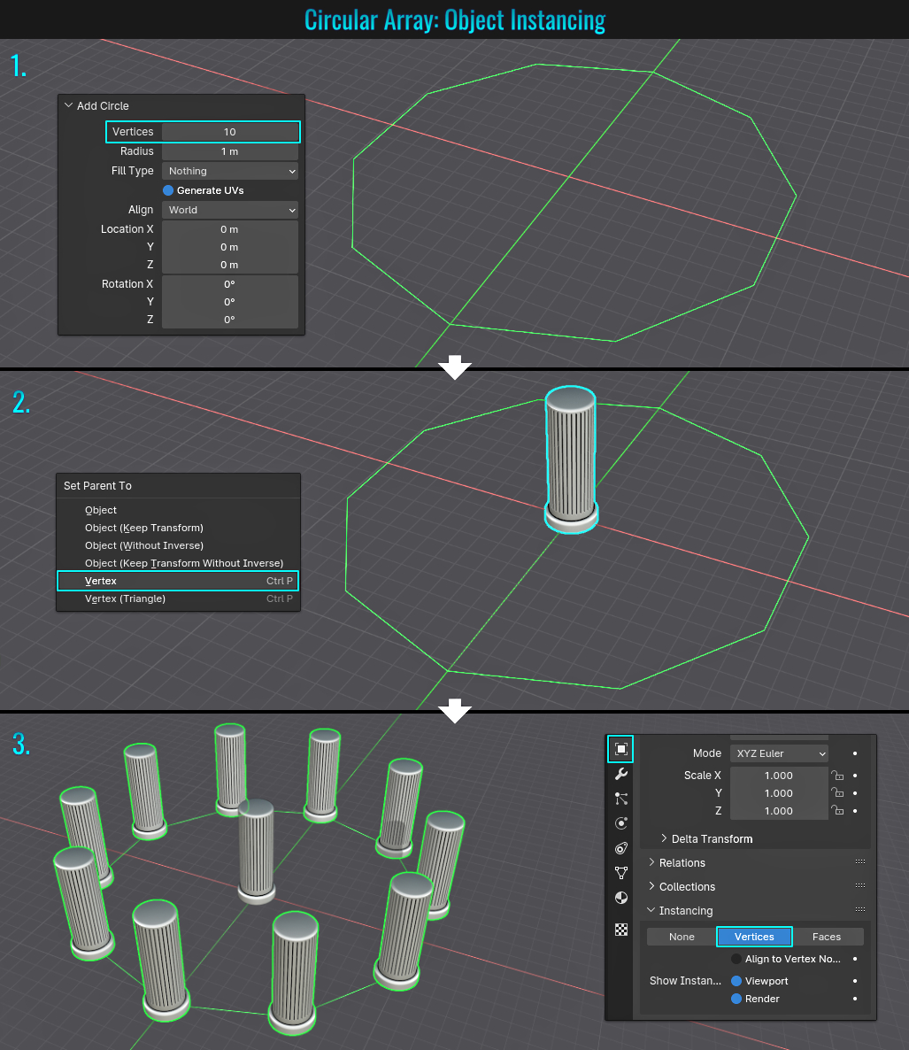
Method 6: Object Instancing
The idea here is simple. Take a mesh and make instances of it across the vertices of a circular object. Let's examine how this can be done in a few simple steps!
- Add a mesh circle (Ctrl + A and choose Mesh > Circle) to your scene. In the Add Circle panel in the lower left hand side of the viewport, set the number of desired sides (say 10 for instance - the amount of vertices will dictate the amount of copies applied) and scale this object to the size needed.
- Next, with nothing selected, first select the mesh you wish to radial array, then hold Shift and click on the circle mesh. Then press Ctrl + P (to bring up the Set Parent To popup) and choose the Vertex option.
- Finally, with the circle mesh selected, go into the Object Properties tab and from within the Instancing panel, click on the Vertices button! Your mesh should now be "radially arrayed" (but more accurately,) using the circle mesh's vertices as the position
points!
The main pillar mesh remains in the center. This can be hidden. If you want to make all these pillars unique separate meshes, with this radial arrayed mesh selected simply goto Mesh > Apply> Make Instances Real from within the viewport's top menu.
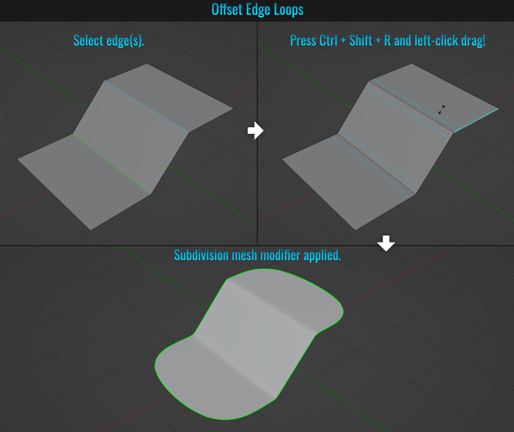
- Offset Edge Loops
You can easily create offset edge loops (which can come in hand when modelling high subdivision meshes) by selecting edge(s), pressing Ctrl + Shift + R and left-click dragging!
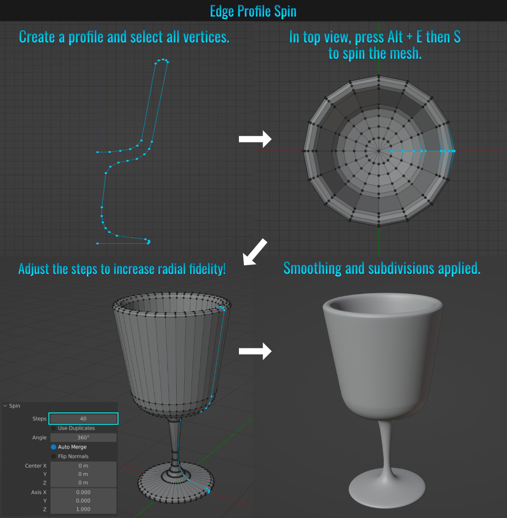
- Edge Profile Spin (lathe)
This is similar to tip #73 (array using the Extrude Spin method) in that the position of the mesh's pivot point matters. In an orthographic view (in this example, front view), start by adding a mesh vertex (press Shift + A and choosing Mesh > Single Vert > Add Single
Vert - You'll need Blender's native Add Mesh: Extra objects add-on installed. Otherwise, add a plane and collapse all vertices into a single vertex and start from there), and in vertex mode, select the point and press E to extrude it.
Continue to extrude
vertices to form a profile shape you want (in this case, a wine glass). Once the profile is completed, simply select all its vertices (double tap A) and from the appropriate orthographic view (in this case top view) press Alt + E then S! This will result
in a 'lathed' mesh! Adjust the Steps value within the Spin operator panel in the bottom left hand corner of the viewport to give more segments!
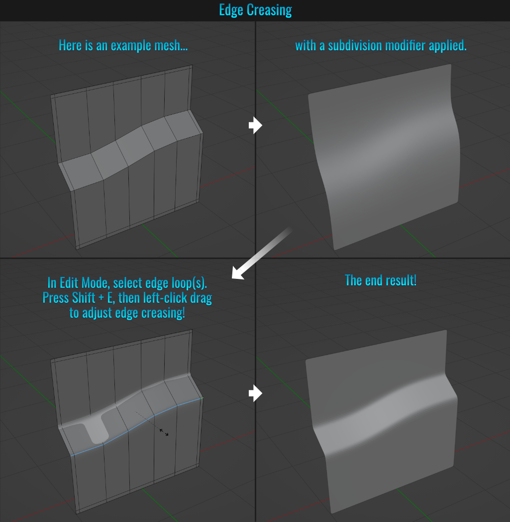
- Edge Creasing
When creating high subsurface division meshes, you can use edge creasing in place of additional edge loops to achieve tighter edged visuals. To do this, simply start by adding a subdivision modifier to your mesh, then with the desired edges selected, press Shift + E and left-click drag to adjust the edge creasing! Simple as that!
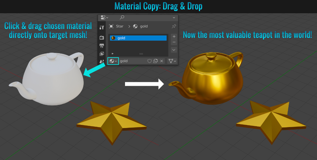
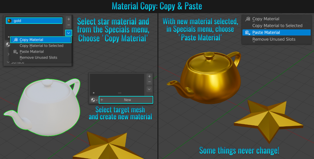
- Copying Materials From One Mesh To Another
When it comes to copying a material from one mesh to another, you have a few options available! In the following examples, the teapot has no material assigned to it, and the goal is to copy the gold star material to it!
Method 1: Drag & Drop
Either:
a) ensure that the material you want is selected via the Browse Material to be Linked dropdown menu -or-
b) simply select the source mesh in question that you wish to copy the material from,
then click-drag the material icon right onto the target model in the viewport!
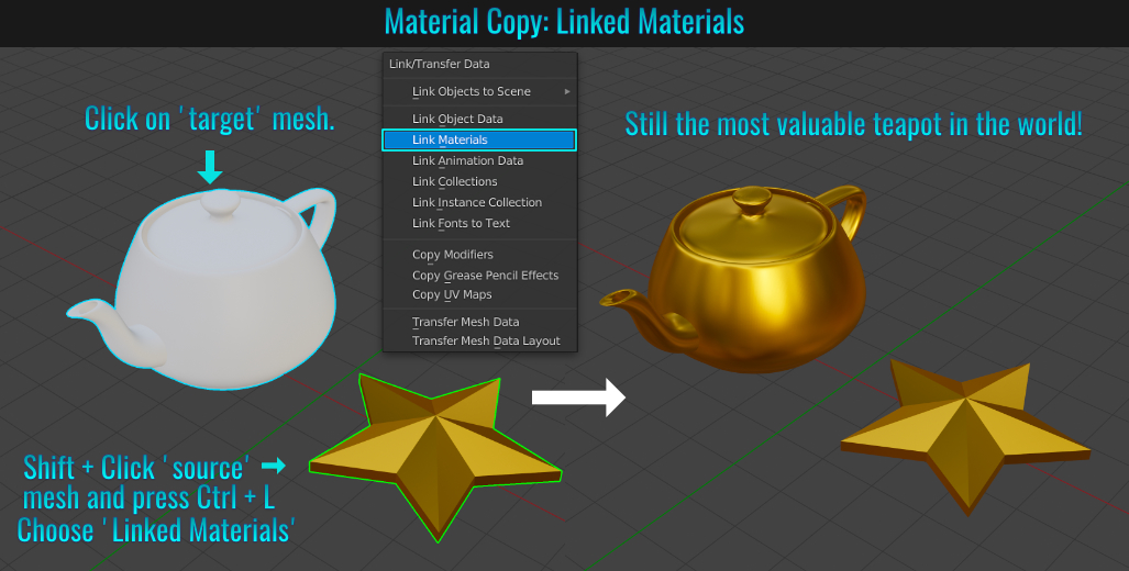
Method 2: Linked Materials
First, select the 'target' mesh (in this case, the teapot), then Shift + click the source mesh (the gold star, which becomes the active mesh). Finally, Press Ctrl + L to bring up the Link/Transfer Data popup and choose Link Materials!
Method 3: Copy / Paste
Finally, there's the good'ol copy and paste! Select the source mesh and then the material you wish to copy, and from the small down arrow (known as the Specials menu) located beneath the + and - buttons on the left hand side, choose Copy Material. Then select the target
mesh and add a new material (by clicking on the 'New' button). Within the Specials menu arrow, choose Paste Material. Now the teapot should be gooooold!
- Triangles And Quads
Sometimes you may find it more advantageous to work with polygons that are either triangulated or quad based. Switching between the two is pretty easy!
Triangles To Quads
- Starting with a mesh that contains triangulated faces, simply go into Edit Mode, select those faces you wish to quadrify and press Alt + J (or this can be accessed via Face > Tris To Quads from the viewport menu).
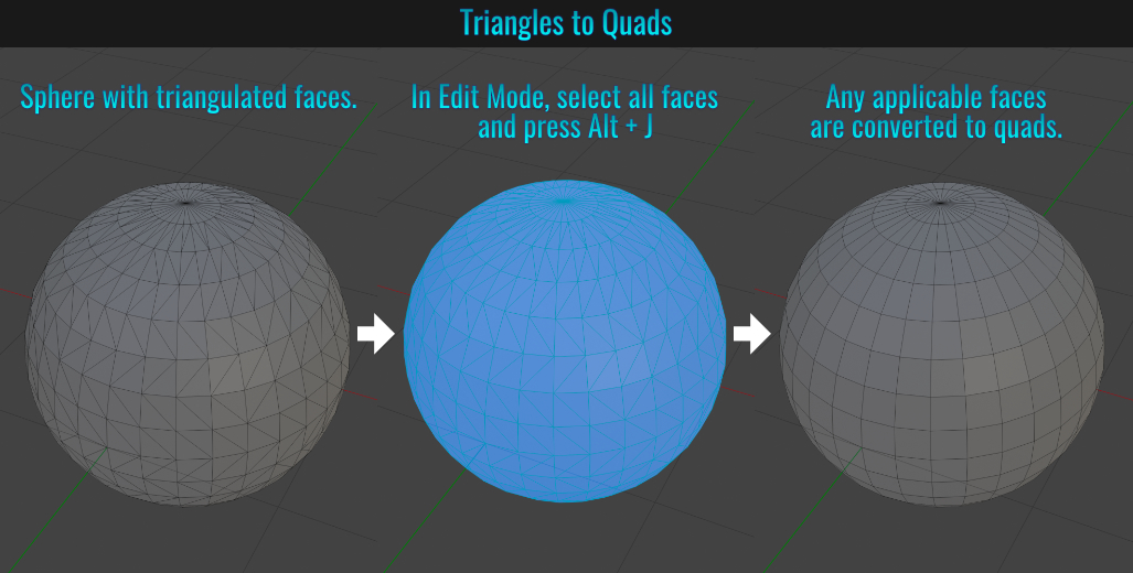
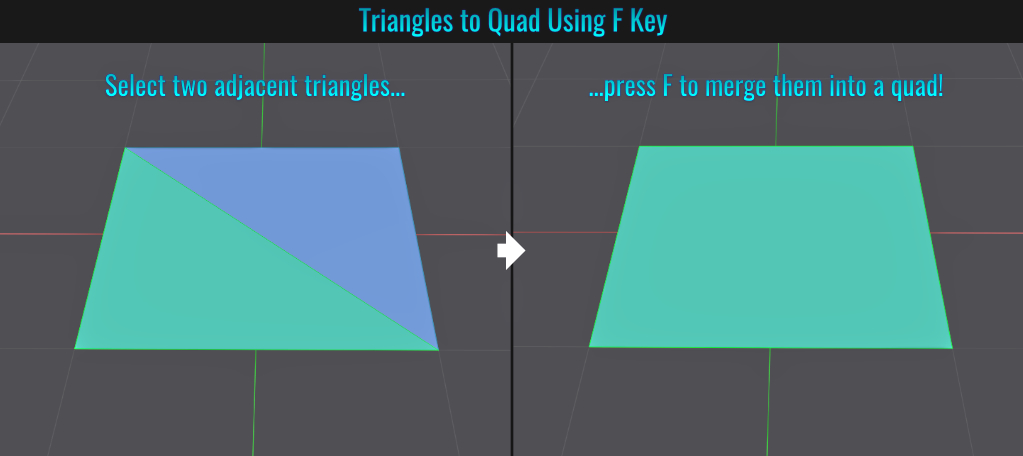
A fun little strategy of converting two triangles into a quad is to select both triangles and press F (the fill tool). Sounds bizarre, but it works!
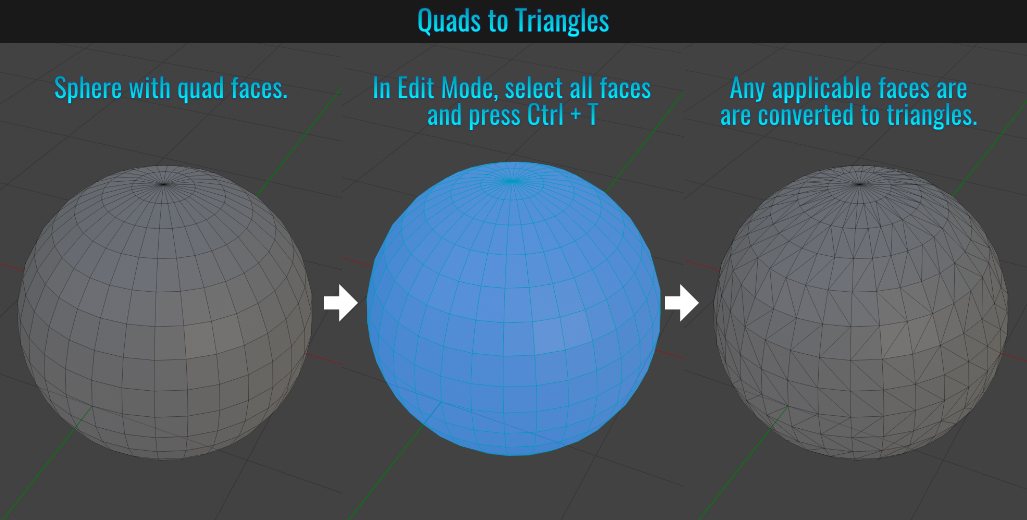
Quads/N-Gons To Triangles
General Triangulation
- Starting with a mesh that has quads or n-gons, simply go into Edit Mode, select those faces you wish to triangulate and press Ctrl + T (alternatively, you can go to Face > Triangulate Faces from the viewport menu).
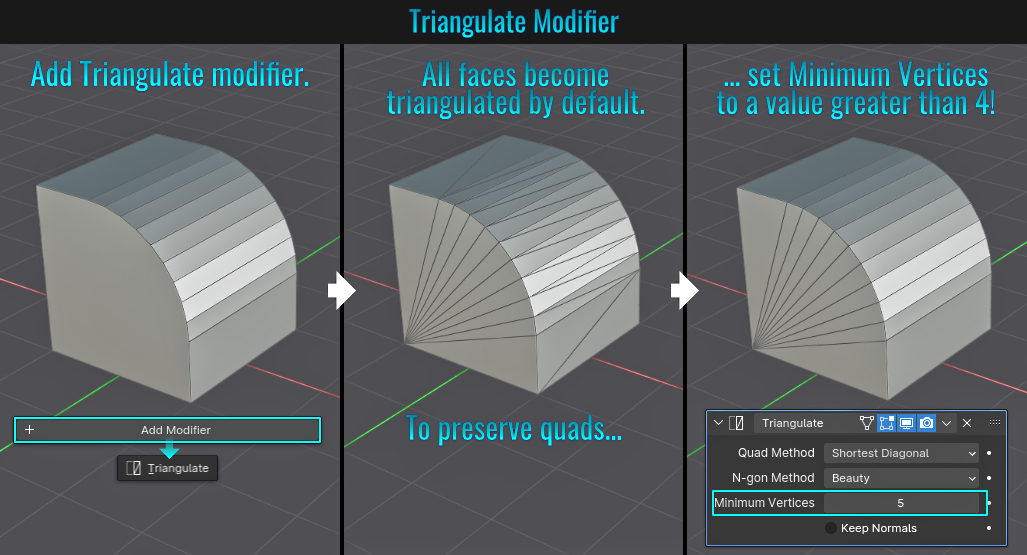
Using Triangulate Modifier
When adding the Triangulate modifier to a mesh, by default it will triangulate every non-triangular face that it can! But you can adjust the Minimum Vertices value to a higher number (which will only target faces set to that
minimum or higher, thus preserving quads or higher)!
- F2 Add-On Fill
The F2 add-on comes with Blender but is not enabled by default. It is a powerful add-on that allows you to fill gaps with polygons. Simply go into Edit > Preferences > Add-ons and type F2 in the search field. Enable the resulting add-on. Fill in holes or missing geo via selections and pressing F.
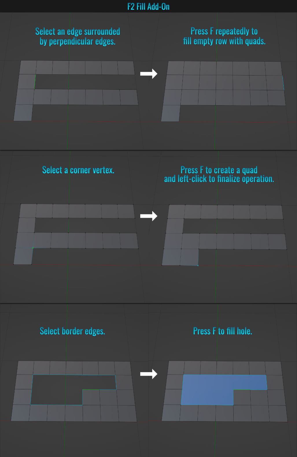
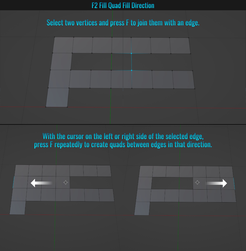
With regards to filling quads using edges, the position of the cursor matters! If two selected vertices are joined to form an edge (pressing F), then with that edge selected, if you place the cursor on the right hand side of this selected edge and press F, quads will fill up in the direction of the mouse cursor!
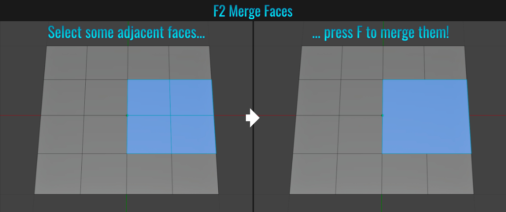
This add-on can also be used to merge faces! Simply select some adjacent faces and press F to merge them!
F2 Adjust UV
By default, the F2 add-on doesn't have the Adjust UV option enabled (this can be found Preferences section below the expanded add-on header info).

As a result, selecting an edge and repeatedly pressing F to quad fill in missing spaces will not properly preserve UVs. With this option enabled however, they will be!

- Random Transform
It's quite easy to apply some random transforms to a series of meshes within your scene. Simply select some meshes and from within the viewport menu, choose Object > Transform > Randomize Transform. The Randomize Transform popup will appear in the lower left hand corner. Simply play with the desired values and watch the selected meshes transform, rotation and scaling alter in real-time!
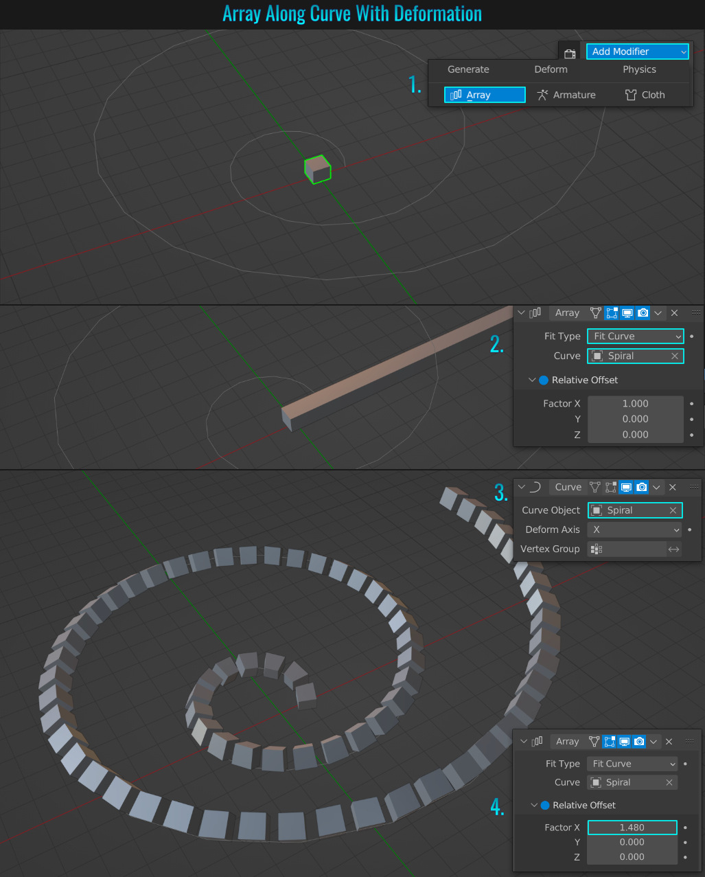
- Array Along Curve
Arrays offer a powerful way of duplicating meshes, especially when a path is involved! In this example, We'll use a cube that will be duplicated along a spiral curve using two different methods. One that results in the cube deforming and other where it does not!
Method 1: Array with deformation
- Select the mesh you want to make an array from and within the Modifier Properties tab, click on Add Modifier and choose Array.
- Set the Fit Type to Fit Curve. From the Curve field, select the curve (by manually picking it or from the drop down list). The mesh array will now tile to be the same length as the spiral curve!
- Next, we need to deform this mesh along the spiral curve. Go back to Add Modifier and choose Curve. From the Curve Object field, choose the spiral curve.
- Finally, back in the array modifier, while holding Shift, drag adjust the amount of the Relative Offset X axis to space them out!
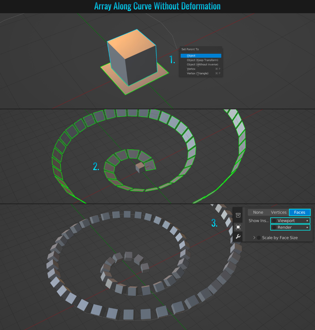
Method 2: Array without deformation
The workflow here is similar to the version above, but with one critical difference! Instead of using the cube as the mesh for applying the array and curve
modifiers to, we'll apply this to a separate parent mesh! So once again, the starting scene starts with a cube and spiral curve.
- Add another mesh to the scene (in this case a plane - but this can be any mesh other than a point). Select the cube, Shift click the plane and press Ctrl + P and choose Object from the Set Parent To popup.
- With the parent mesh (plane) selected, go through the same process as method 1. Once done, the end result it a plane that is the array object following the spiral curve.
- With the parent mesh still selected, make the cube visible (and the parent invisible) by going to the Object Properties tab and from within the Instance panel, choose Faces and simply un-checking the radial boxes for both Viewport and Render in the Show Instancer section! Notice now that the child mesh (in this case, the cube) is not deforming as it follows the curve! Hide (or get rid of) the initial cube.
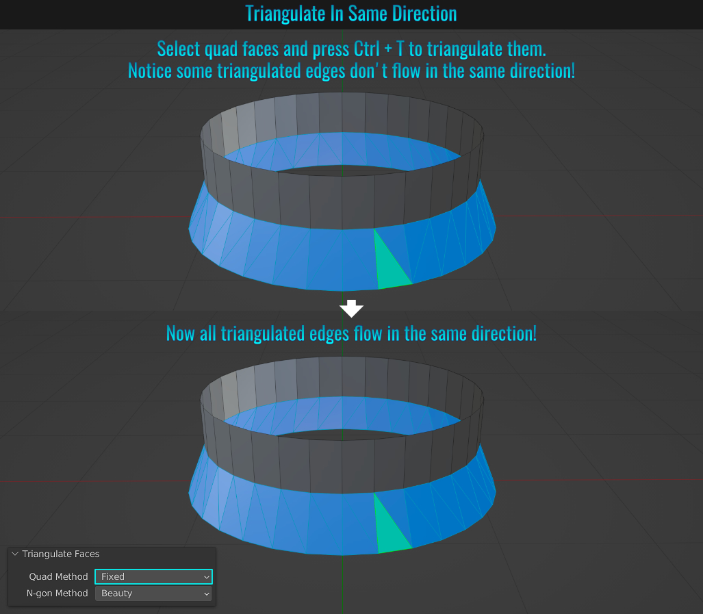
- Triangulate In Same Direction
When converting quads to triangles, some of the triangulated edges might be rotated against the general flow. The solution to have them all flowing the same direction is easy. Start by selecting some quad faces and pressing Ctrl + T to triangulate them. In the Triangulate Faces panel in the lower left hand side of the viewport, switch Quad Method from Beauty to Fixed. Now all triangulated edges should flow in the same direction!
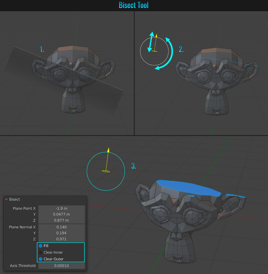
- Bisect Tool
Blender has tools that allows us to cut straight through a mesh. The knife tool can accomplish this, but is very limited, in that it only performs a cutting operation. The bisect tool by contrast, while only allowing straight cuts, allows to reposition the cut, as well as remove the
top or bottom portion and fill in the hole of the remaining portion! Lets add the monkey mesh as an example and see how this works.
- Select all mesh faces (pressing A twice) and from within the viewport menu along the top, choose Mesh > Bisect. Left click-dragging through the mesh establishes the cut line.
- With the line established, the bisect gizmo allows the line to be moved and/or rotated!
- Within the bisect panel in the lower bottom left of the viewport, you can choose between Clear Inner, Clear Outer and whether there is a Fill applied or not!
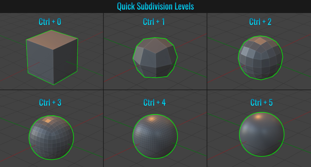
- Quickly Add Subdivision Levels
While you can manually add a subdivision modifier to your mesh, Blender offers six levels of subdivisions as shortcuts. Simply select your mesh and press Ctrl + 1 thru 5 with 0 representing no subdivision levels at all! It's that easy!
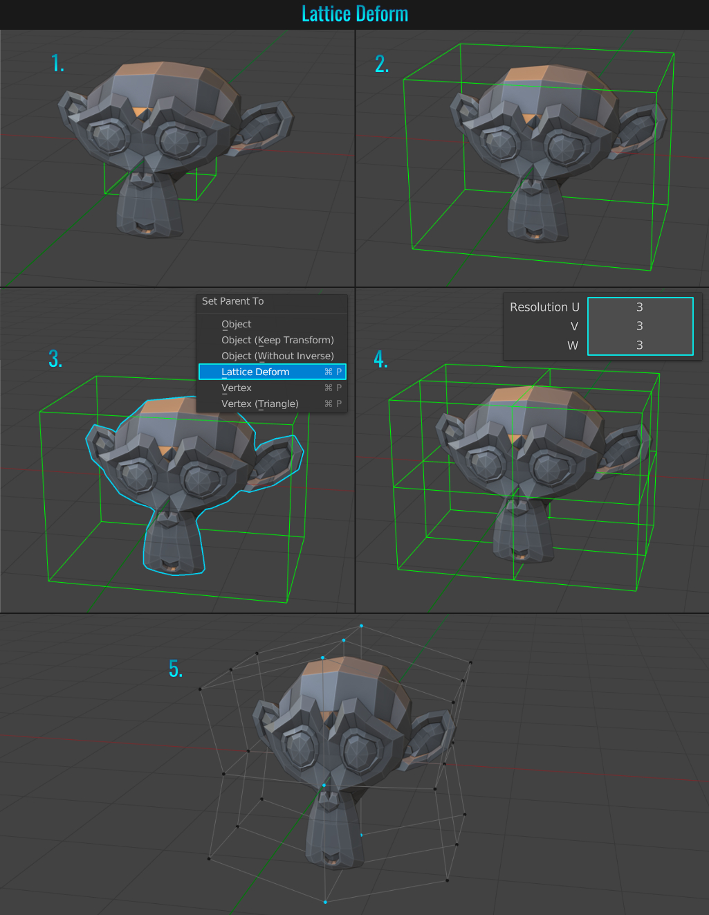
- Lattice Deform
Adding a lattice to deform your mesh is pretty easy and straight forward! Let's use the Blender monkey head as a starting scene!
- Press Shift + A and choose Lattice from the Add popup.
- Scale/Move the lattice to fit the mesh in object mode! It is very important you do NOT resize the lattice in edit mode, as this will ultimately give incorrect results!
- Select the monkey mesh, then Shift + Click the lattice mesh. Press Ctrl + P and choose Lattice Deform from the Set Parent To popup (a lattice modifier is automatically added to the monkey mesh!)
- Optional: Select the lattice mesh and from the Lattice tab (
 ), adjust the U,V and W resolution to add more vertices to the lattice for more deformation control!
 - In edit mode, select lattice vertices and manipulate them to deform the monkey mesh!
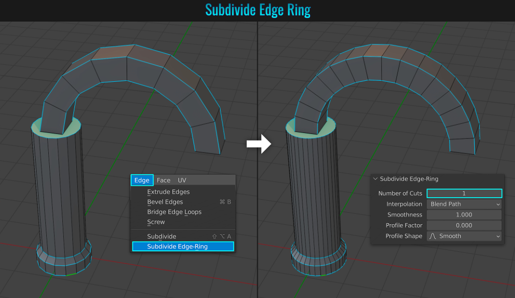
- Subdivide Edge Ring
Sometimes you might make a cylinder or say an arch that is too low in poly count. It is possible to not only increase the segments, but have those new segments follow the curve of the surrounding existing segments as well! Using the example scene of a pillar and arch, let's see how
subdivision edge rings can solve this! Start by ring selecting the edges needed to increase in resolution.
In many cases, edge loop selections will work as well. Just be sure that matching opposite edge loops are also selected, otherwise you'll get undesirable results! From the
viewport top menu, choose Edge > Subdivide Edge-Ring. In the operations panel in the lower left side of the screen, the Number of Cuts setting defaults to 10. Simply alter this to get different results (a setting of 1 doubles the segments).
You might need to apply transforms to your mesh before hand for this tool to function properly!
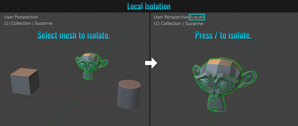
- Local Isolation
Sometimes a Blender scene can get rather cluttered with meshes. And with this comes the need to be able to isolate the mesh you are working on. This can be done by selecting a mesh in question and simply pressing / or numpad /. This puts the scene in Local view, zooming in on the selected mesh while hiding everything else! Pressing either shortcut again brings back all previously visible meshes as well as returning the viewport view to its previous state.
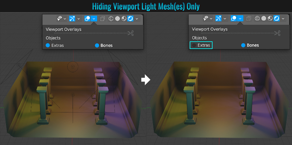
- Extras: Hiding Lights
There comes a time in a person's life when they need to hide light mesh(es), yet keep the lighting active in the viewport! Luckily, this is easily done by simply un-checking Extras from within the Overlay menu! The viewport light mesh(es) will be hidden, yet they continue to light your geometry!
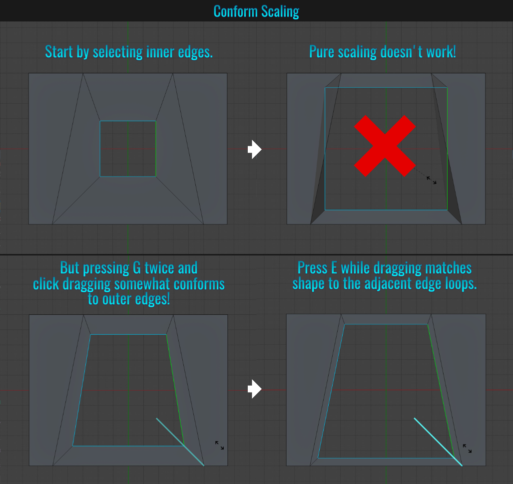
- Conform Scaling
If you have some inner edges (say a hole for example) and you want to scale these edges up while keeping them conforming to the outer edges (which are not square), simple scaling won't work! But by double tapping G and click dragging, the inner edges will scale and start conforming to the outer edges! In this state, you can press E to force the inner selected edges to more accurately conform with the outer edges!
- Scale Cage
While not quite as flexible as a lattice deformer, Blender's Scale Cage offers a cage with a series of control points located around it to scale the selected mesh in question with ease. Simply long press the scale icon along the left hand side bar (if no icons are visible, simply press T to bring them up) and switch the scale to scale cage. Now when you select a mesh, you can scale it via the cage's control points!
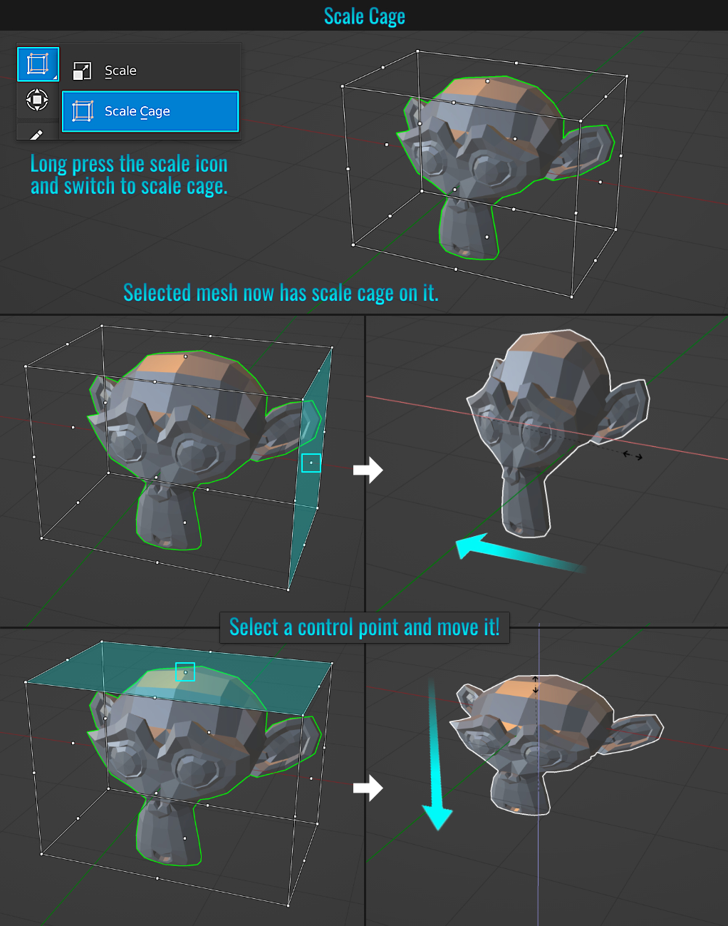
Note: When click-dragging any corner control point, the mesh uniformly scales in the direction of the opposite corner!
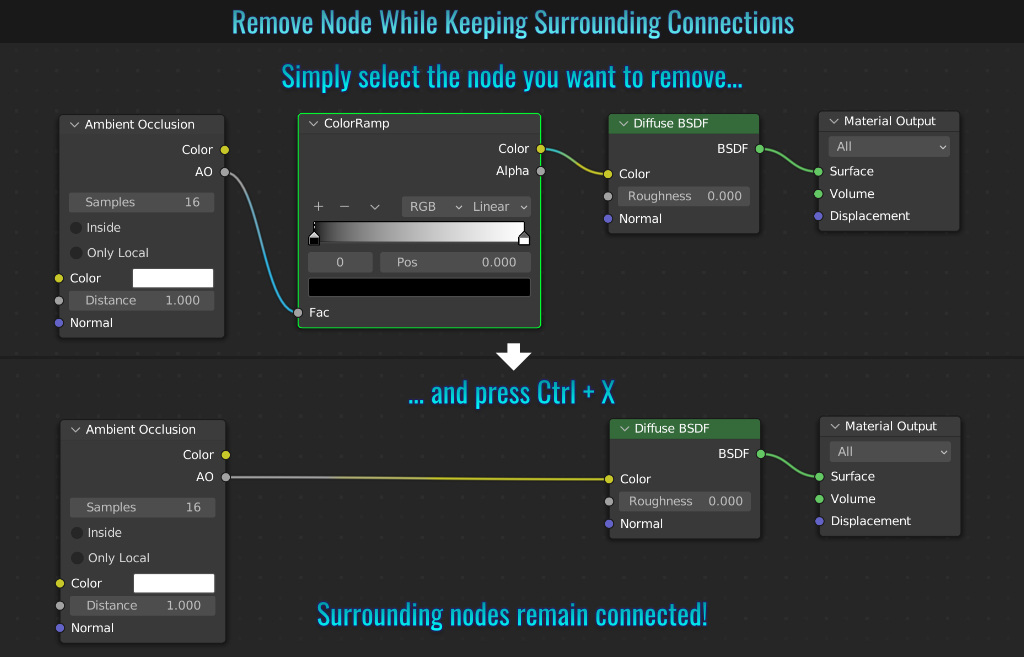
- Remove Node While retaining Connections
Sometimes you'll need to remove a shader node, but you'll want to keep the surrounding node connections. Instead of manually deleting the unwanted node and reconnecting other nodes back, simply select the node you want to remove and press Ctrl + X. This will automatically keep the connection between the other surrounding nodes while removing the target node!
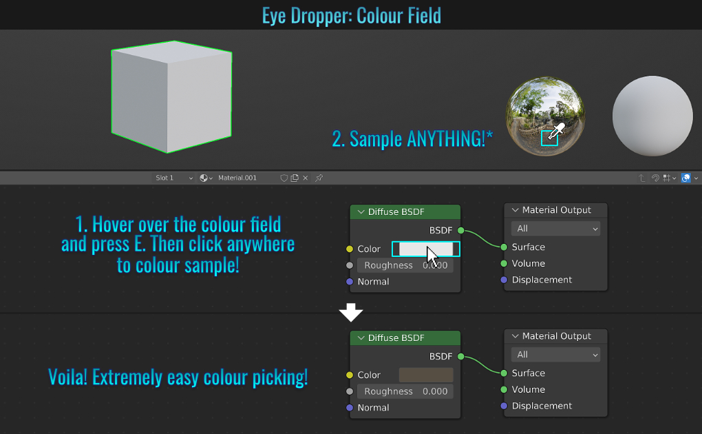
- Colour Field/Gradient Eye Droppers
Blender allows you to use the eye dropper when dealing with any colour fields or gradients to effortlessly choose the colour(s) you need!
Colour Field
- Simply hover your mouse cursor over a colour field and press E. Your cursor becomes an eye dropper! Now you'll be able to click-sample anywhere onscreen and the field will be replaced with whatever colour value you click on!
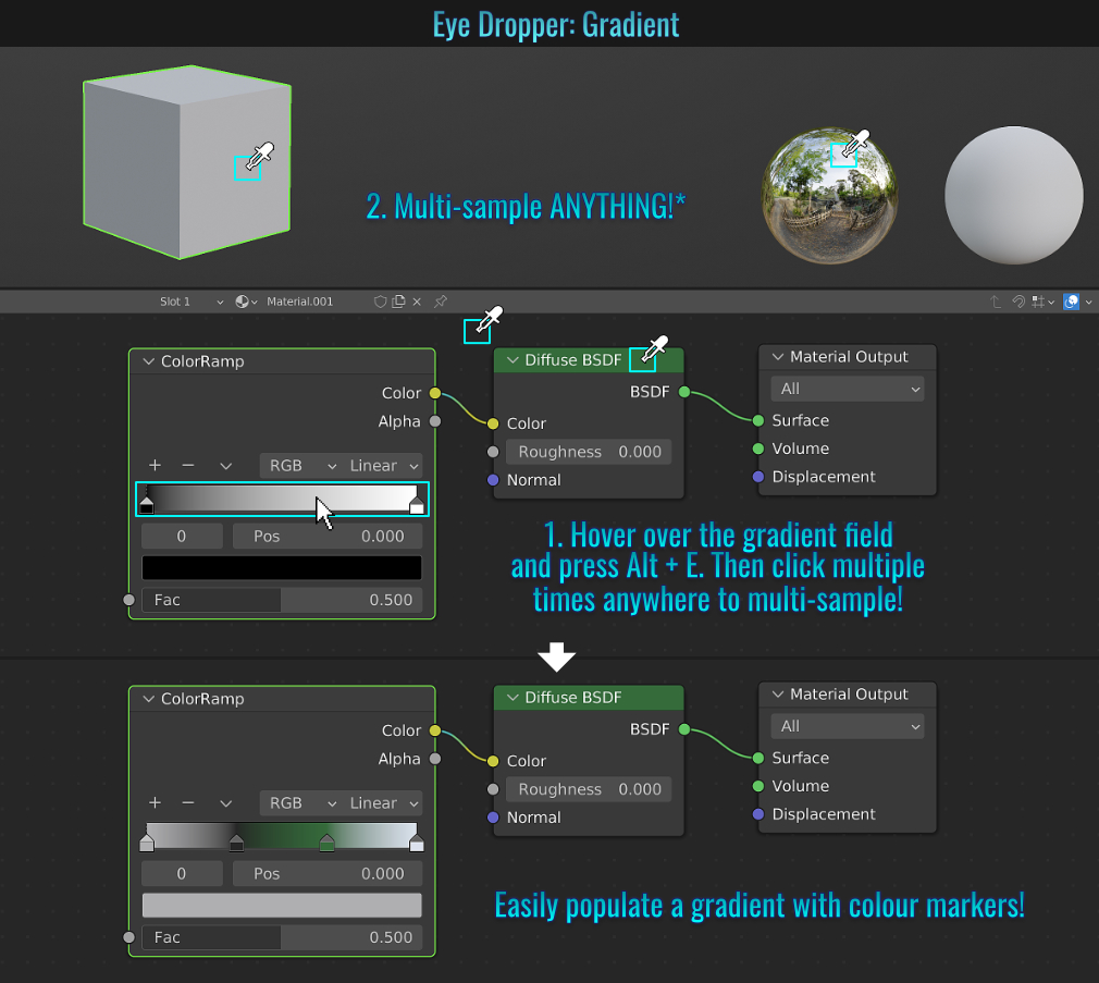
Gradients
- Hover your mouse cursor over a gradient and press Alt + E. Once again, your cursor changes to an eye dropper! Now you'll be able to click-sample multiple times anywhere onscreen and the gradient will automatically add any additional colour stops as needed with whatever colour values you clicked on!
Bonus note: If you press E over a gradient field and then click and drag, the gradient will auto populate with colour stops!
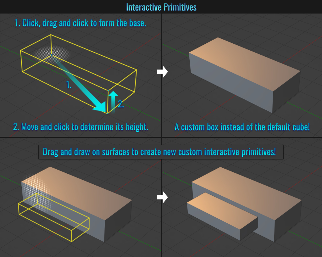
- Interactive Primitives
Primitives aren't limited to those found in the Add popup (Shift + A). Along the left side icons in the viewport (if they're not visible, press T to bring them up), locate the Add Cube icon. This is the primitive interactive cube
(by default - long pressing on the Add Cube icon reveals a small drop down of additional primitives, each with their own click and drag functionality to set up their dimensions!). Clicking on this converts the mouse cursor within the viewport to a circular grid with a fall off. In this mode, you can
simply click and drag to start the width/length of the cube.
Once you left click, move the mouse cursor up or down and click to determine its height.
- Negative Lighting
Did you know that lights can have negative power values? This is a great way to darken corners in a room for example. If exploited properly, negative lighting can be very effective and useful!
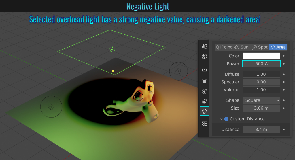
Side Note 2: While Suzanne (the monkey head) puts on a brave smile, her eyes look kind of sad... scared even!
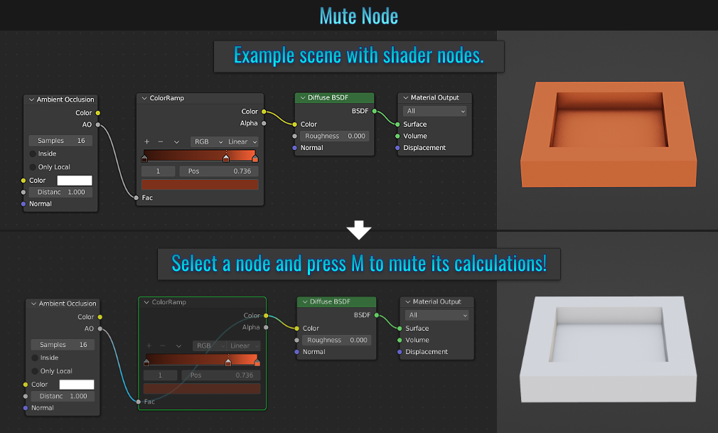
- Muting Shader Node
One of many useful features in the Shader Editor is the ability to mute nodes! By selecting a node and pressing M, the node in question remains connected but is muted, meaning it will not be included in the node calculations!
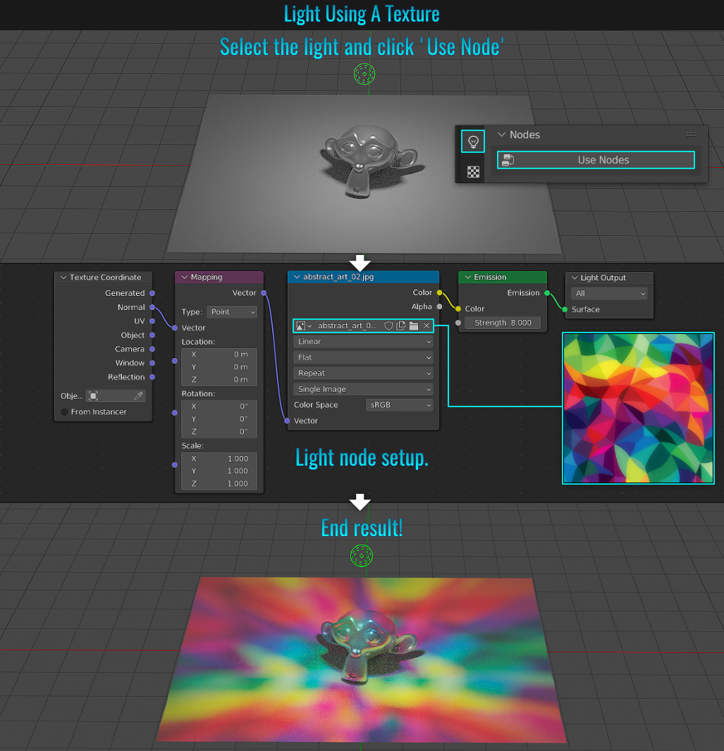
- Textures In Lights
Did you know that a light can use a texture to colourize (or shade) a scene? Ensure that the Cycles rendering engine is chosen and that the viewport mode is set to Rendered. Simply select the light in question, and from within the lighting tab, click on Use Node. Jump into the Shader Editor, and set it up according to the screenshot and voila! The chosen texture tints everything within the light's range! This can be additionally useful for faking shadows of tree foliage on the ground from a spot light for example. The possibilities are endless!
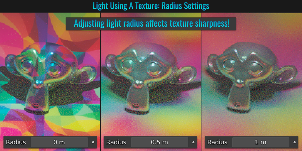
The light's radius setting affects how sharp the projected texture image is. Lower values are sharper while higher ones are blurrier!
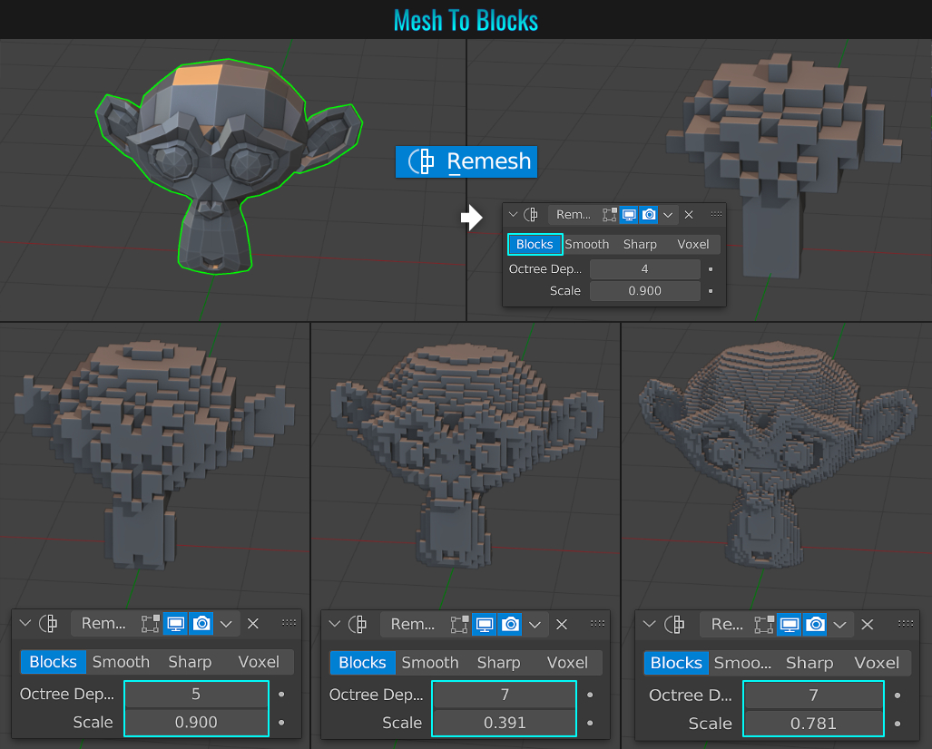
- Mesh To Blocks
Have you ever wished to convert a mesh into blocks that resemble something like in Minecraft? It's pretty easy in Blender. Simply select the mesh in question and throw a Remesh modifier on it! Then switch the modifier's mode to Blocks and play with the Octree Depth and Scale values!
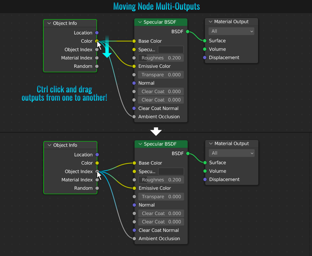
- Moving Node Multi-Outputs
Sometimes you might want to move a node output (that branches off to other nodes) to another output on the same node. It's quite simple to do! Simply hold Ctrl and click on the multi-output you want to move and drag it onto another output!
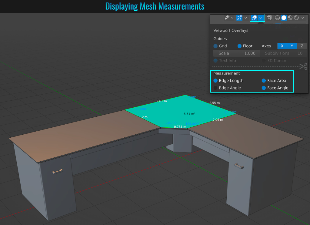
Prototyping something in Blender and want to see some mesh dimensions? Simply be in Edit Mode and from within the Overlay dropdown above the viewport, look towards the bottom and simply apply which types of measurements from the Measurement section! For proper measurement readouts, ensure beforehand that your mesh has a scale value of 1 (this can be checked by pressing N to bring up the right hand side panel and looking at View tab, make sure all scale values are set to 1. If they are not, apply scale to your mesh by going into Object Mode and choose Object > Apply > Scale).
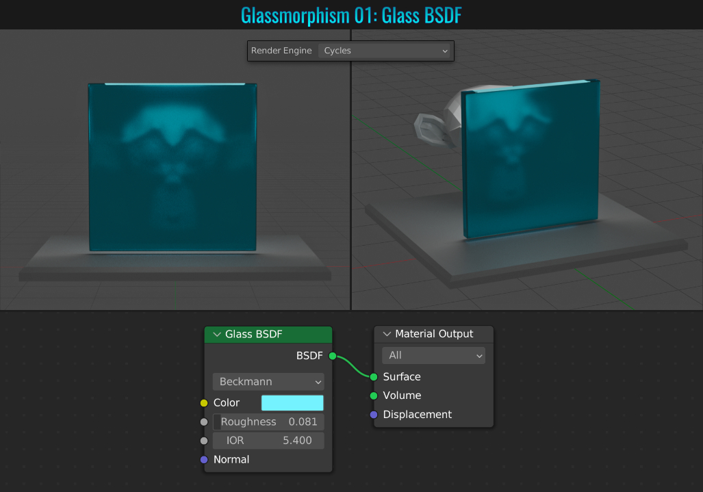
- Glassmorphism
What is Glassmorphism? It's a trend in user interfaces where a plane of glass (taking on a frosted look) overlays a background. This effect is quite easy to do in Blender! Our background example will be the monkey head on a platform and a thin sheet of glass (simply a beveled
cube scaled thin). The methods below achieve this look and feel but each one offer varying degrees of control!
Method 1: Glass BSDF
This first version is the simplest, yet gives minimal control! Aside from the output, the Glass BSDF shader node offers the choice of microfacet distribution, colours, roughness,
IOR as well as a normal input.
You can read more about this shader here. This method requires you to set the rendering engine to Cycles.
Method 2: Principled BSDF
Using the Principled BSDF node, you have more control! In addition to the first method's parameters, you can play with Metallic and Transmission values among others! Of course, you have the entire node parameters at your disposal!
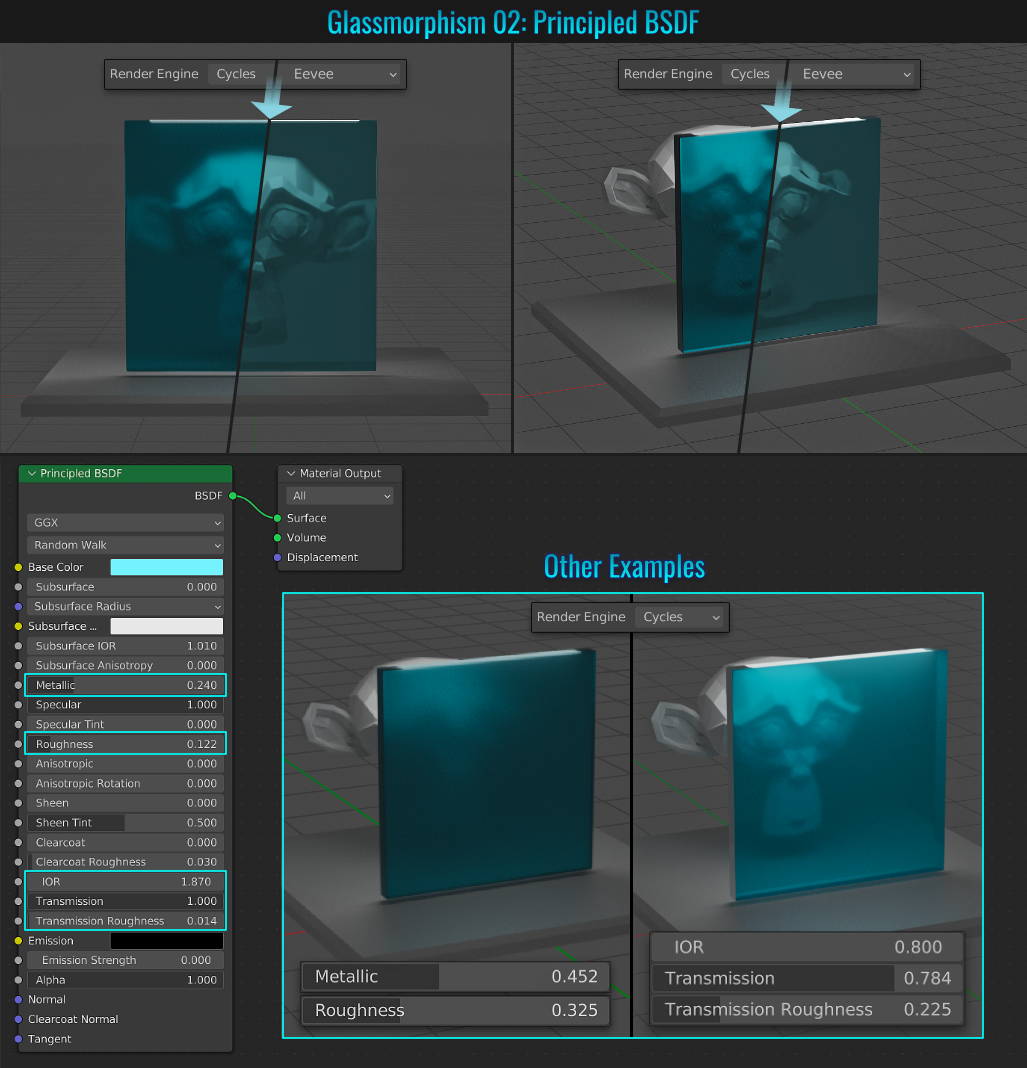
Method 3: Various Nodes
This method offers the most options with the addition of Noise, ColorRamp more!
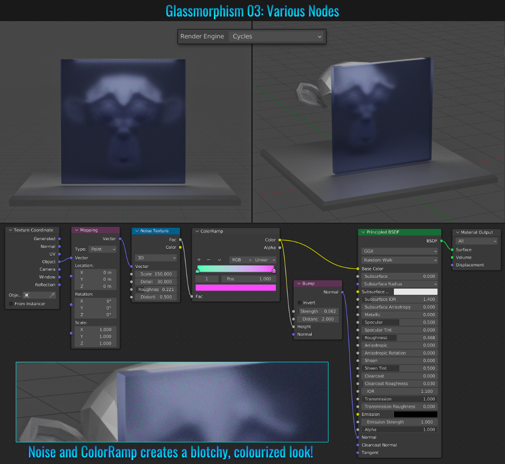
- Image As A Plane
Unlike in the tip Reference Images where a reference plane cannot be modified other than uniform scaling, it is sometimes desirable to be able to bring an image directly as a regular old fashioned plane where you can do any kind of geometric
modifications to it! The real benefit here is adding an image plane without a fuss!
So instead of manually creating a material with the texture as its image, then creating a plane and assigning that material to it, simply enable Blender's built-in Import-Export: Images as Planes
add-on. From now on, when you access the Images sub menu from within the Add menu (Shift + A), you'll notice the Images as Planes option. Choosing this will add a plane in the scene with an auto assigned material using the chosen image as
its texture! Much faster and easier!
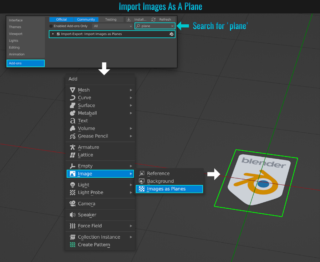
Dealing with a scene with plenty of meshes with high subdivision modifier viewport levels can really bog down your computer. By going into the Render Properties tab, enable the Simplify option and open it up to view both viewport and render Max Subdivision settings. Here, you can globally override all mesh subdivision modifiers by setting the viewport/render max value to something respectable like say 1! Now you'll be able to toggle the Simplify setting without the need to adjust each mesh's subdivision modifier values!
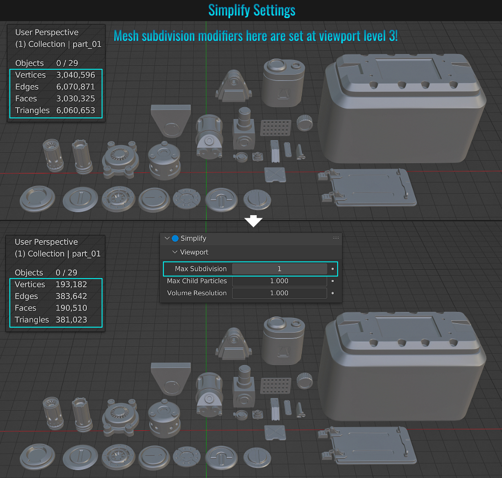
- Display UV Stretching
An easy way to see if your mesh has UV distortion is to enable Display Stretch from the Show Overlays dropdown along the top upper right side above the UV Editor window.The default setting within the Display Stretch Type is set to Angle, but you can also set it to Area. Blueish tinted faces represents very low to no distortion while yellowish to orangish represents varying degrees of distortion!
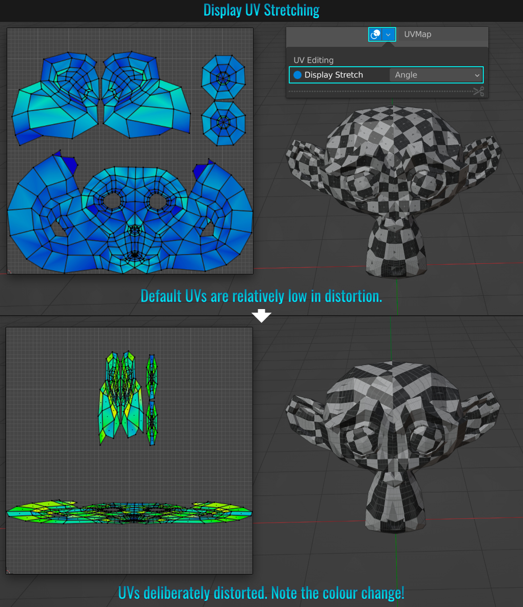
- Fixing Beveled Corner
There might be some situations where beveling multiple edges that include an inner corner causes undesirable results. Whether you are using the bevel modifier or simply using the bevel shortcut, setting the Miter Outer to Arc will set the beveled inner corner to have an arching radius that is more often than not the desired outcome!
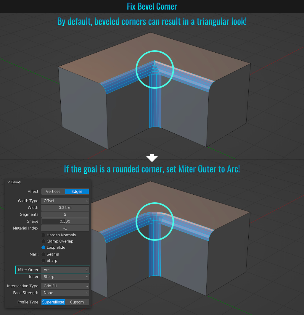
- Node Groups
Node grouping is a way of categorise multiple selected nodes into a single one. This grouped node (aside from an organizational standpoint) can also be reused elsewhere in the shader editor! Creating a node group is fairly straight forward!
Simply select the
nodes you wish to make a group of and press Ctrl + G. To un-group, simply select the group and press Alt + Ctrl + G. When a group is created, its title contains a group icon
(![]() ) that can be clicked on to open the group.
) that can be clicked on to open the group.
Once inside the group, you can click the Parent Node Tree curved up arrow button found along the top right hand
side of the shader editor. Likewise, you can also jump in and out of node groups by pressing Tab. Pressing Ctrl + Tab will only bring you out of the group! Once the group is opened, the shader editor only displays the group nodes. Finally, it's important to note
that groups should not contain input or output nodes, nor can groups be nested!
You can read more about node groups here!
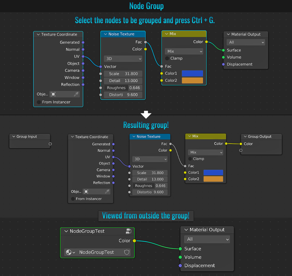
It is possible in Blender to create a clipped view by simply pressing Alt + B and click-dragging a rectangular region in the 3d viewport. When orbiting/panning/zooming in the view, you'll notice that there is a "clipping frustum" based on the region that offers an x-ray/geo clipped effect on the scene mesh! Press the same shortcut again to exit this mode!
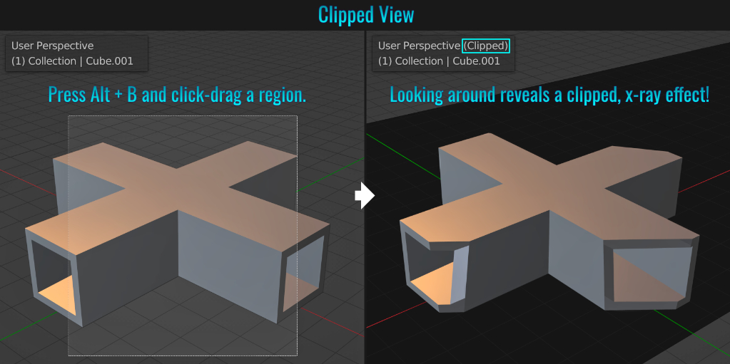
- Cycling Proportional Mode
You can cycle through the various proportional editing modes while the tool is active! Start by making a selection on your mesh and press O to enable the proportional tool. Next, press G and while the selection is moved (don't click to finalize the move), simply hold down Shift and continuously press O to cycle through the various proportional tool's modes (not all modes are represented here).
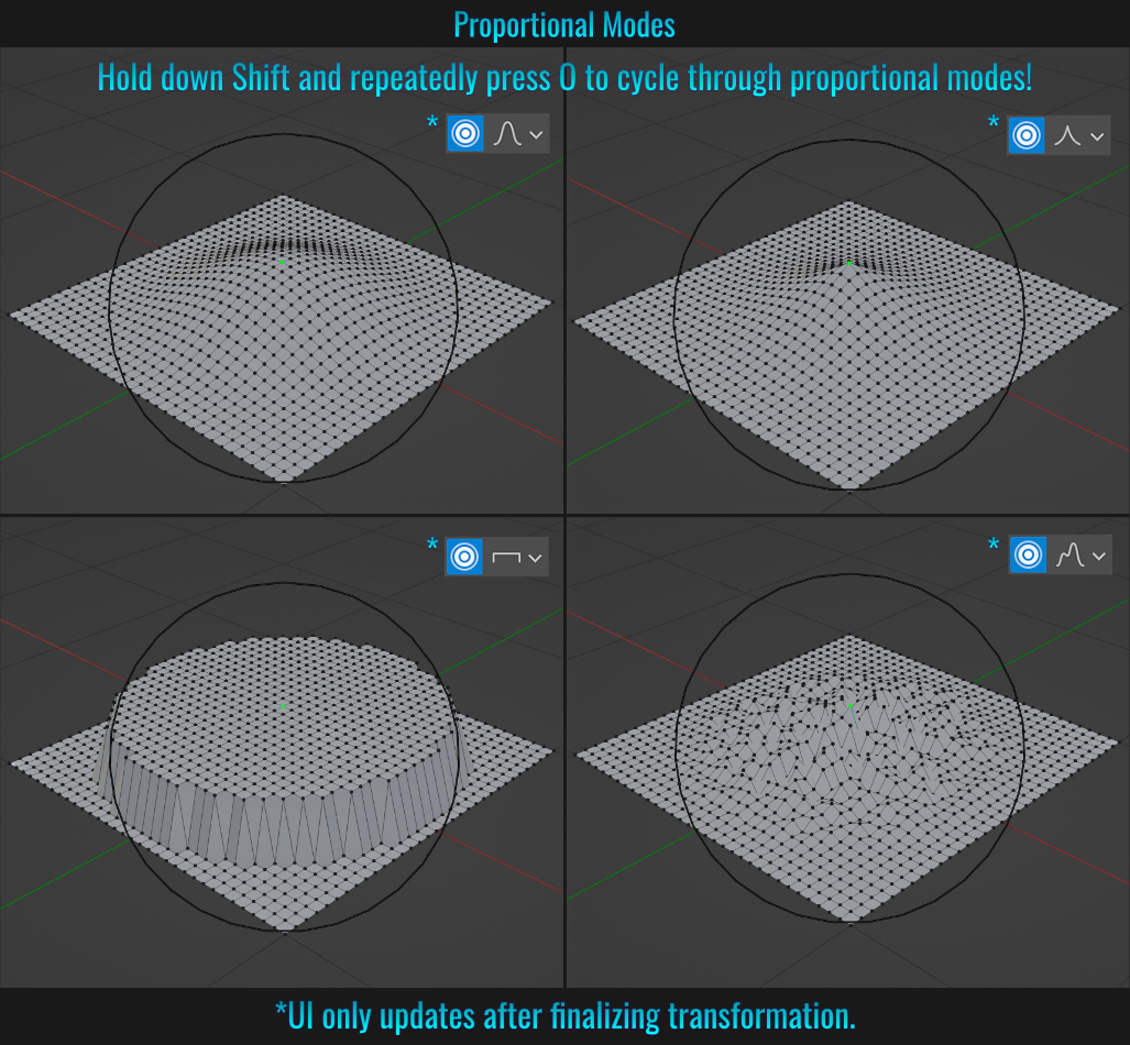
- Drag & Drop From Outliner
Did you know that you can drag and drop a mesh from the Outliner directly onto another mesh in your scene and it will snap to the other mesh's surface? Ensure that your mesh has a proper origin placement and apply transforms beforehand for best results!
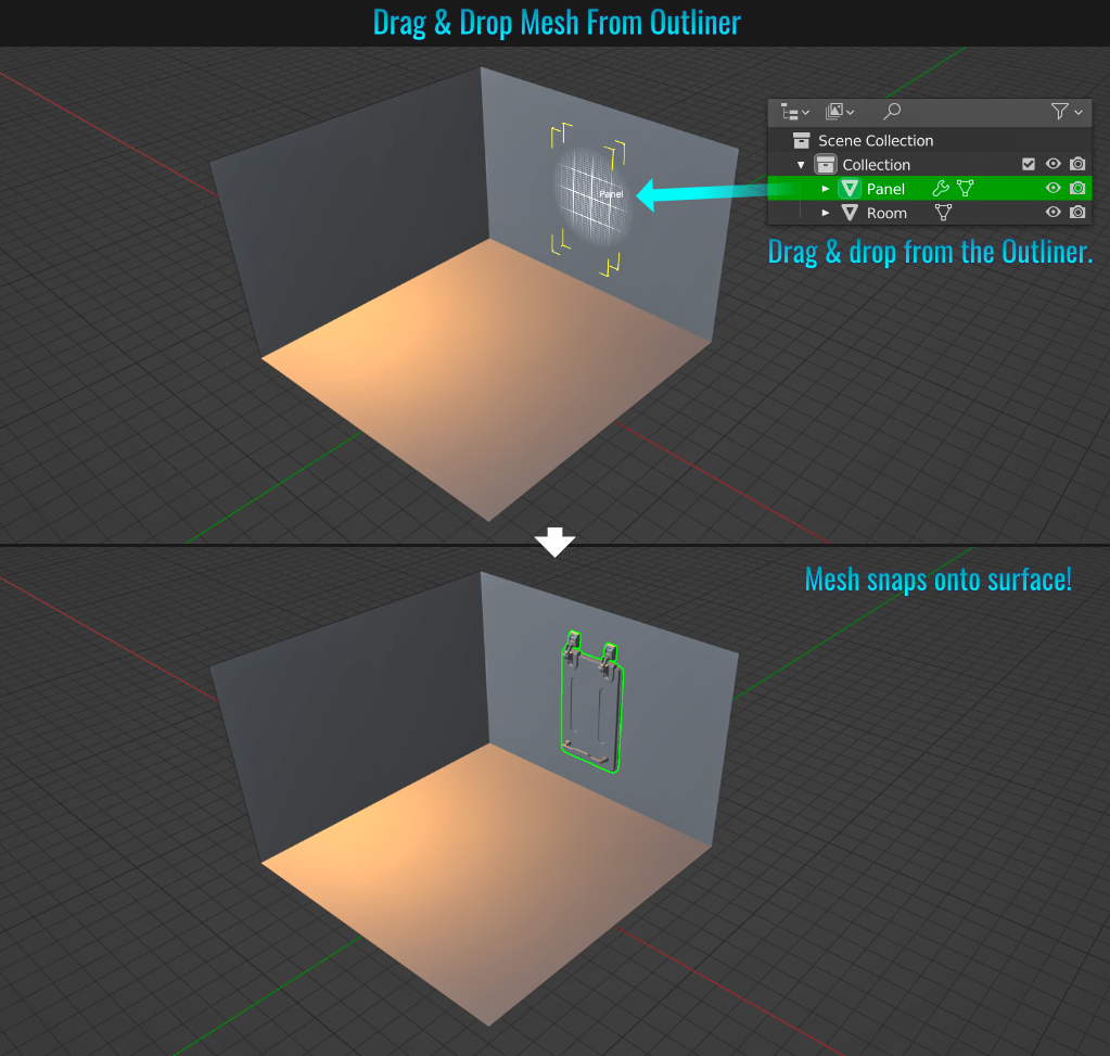
When you have meshes parented to other meshes, simply select a mesh and use the [ or ] keys to navigate-select through their parent/child relationships! This could be useful when dealing with complex hierarchies where it might be easier to select one of the meshes in the chain and navigate from there!
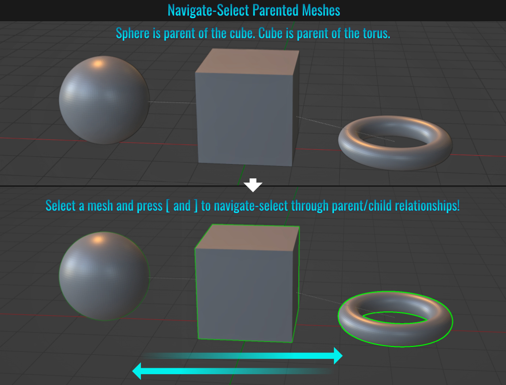
- Convert Mesh Selection To Convex Hull
If you have ever needed to create collision meshes for in-game assets, this just might be the tip for you! Select a portion (or the entire) mesh in question and choose Mesh > Convex Hull from the 3d viewport menu!
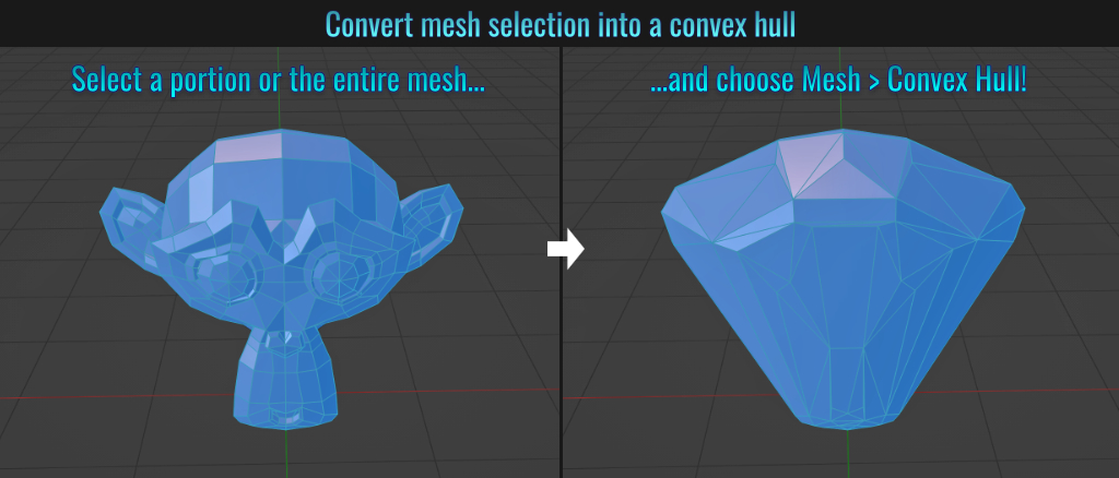
- Select Pattern
When trying to select multiple related meshes (copies or instances) in a jumble of other meshes, life is easy if you do two things:
- Ensure that mesh base names are somewhat useful and similar.
- Select one of the meshes, and from the 3d viewport menu, choose Select > Select Pattern... and enter the base name of the mesh followed by an asterisk (known as a wildcard in search parlance)!
This will result in quickly selecting all meshes related by base name!
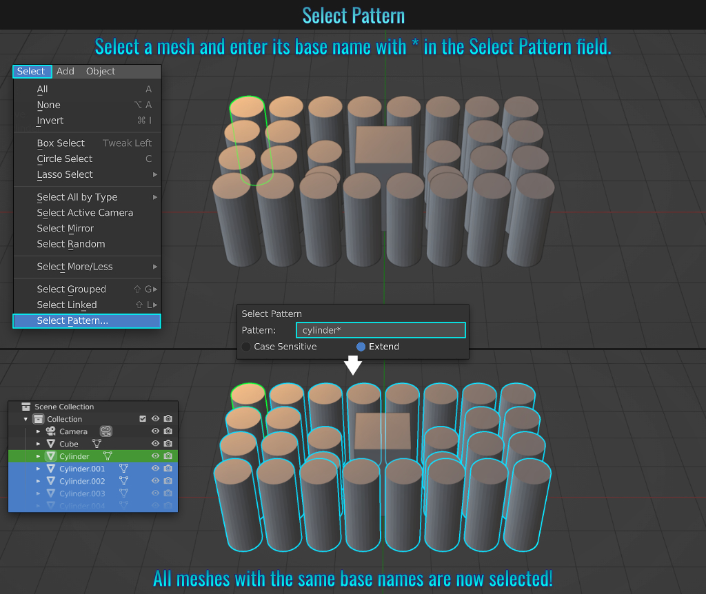
- Adjusting Identical Node Values
You can adjust the same value in two nodes at once by selecting them, then holding down Alt and dragging said value (doesn't work if you have Emulate 3 Button Mouse enabled!) If the fields in question have different values to begin with, the difference will be maintained while changing one of them!
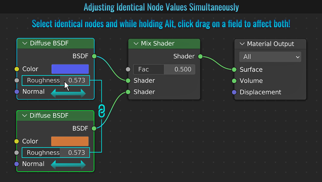
When testing out how bright a scene is, first ensure that your viewport shading mode is set to Rendered. Then simply navigate to the Render Properties tab, and from within the Color Management panel, switch the View Transform option to False Color! Any lighting effects on a mesh that is over powered will show up as shades of red! Green and blue shades are safe (not over blown!) While in this mode, feel free to go into the Output Properties tab and from within the Color Management panel, play around with the Exposure slider to adjust the scene's exposure in real time! The aim here is to try an get most objects in the green / blue part of the spectrum.
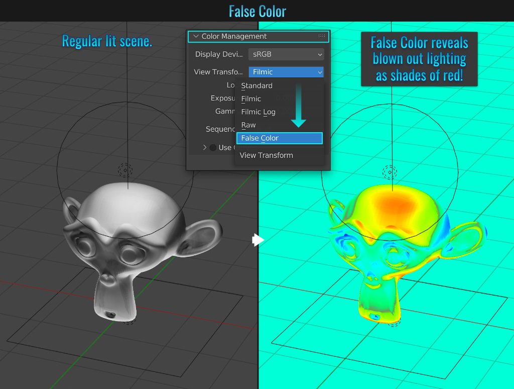
- Center Content
A quick way to center the content in your viewport is to press Shift + C! This not only frames your scene objects, but it resets the 3d cursor to world origin as well! Optionally, you can press Home to frame content without resetting the 3d cursor!
- Breaking Off Selections
While you can press P (and choose Selection from the Separate popup) to break a mesh selection off into its own mesh, you can press Y to break a selection off but keep it as part of the mesh it belongs to!
Within the sidebar menu (press N to bring it up), you can pin any panel by right-clicking it and choosing Pin (or by pressing Shift + LMB). Now that pinned panel will show up in any tab you select! Right-click again on the panel in question and uncheck the Pin checkbox to unpin it!
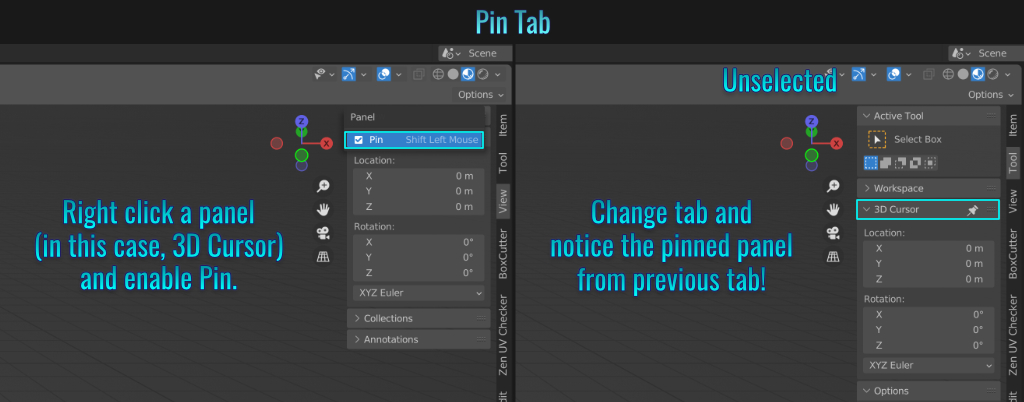
- Link/Data Transfer
Select multiple objects and press Ctrl + L to bring up the Link/Data Transfer popup. From here, you can link things like materials (see tip Copying Materials From One Mesh To Another) or Object Data
where one mesh visually becomes the same as another mesh!
The benefit here is that since all meshes involved will be linked to a singular under the hood data block, this in effect acts like an instance! So modifying one linked mesh will affect all other linked meshes as well! Additionally,
you can use this menu to copy modifiers from one mesh to another among other features! Pretty handy stuff! You can read more about data blocks here!
- Loop Cut Smoothness
When loop cutting, it is possible to give the cuts some shape by adjusting the smoothness and falloff settings in the Loop Cut and Slide operator panel found in the lower left hand viewport panel while the tool is live!
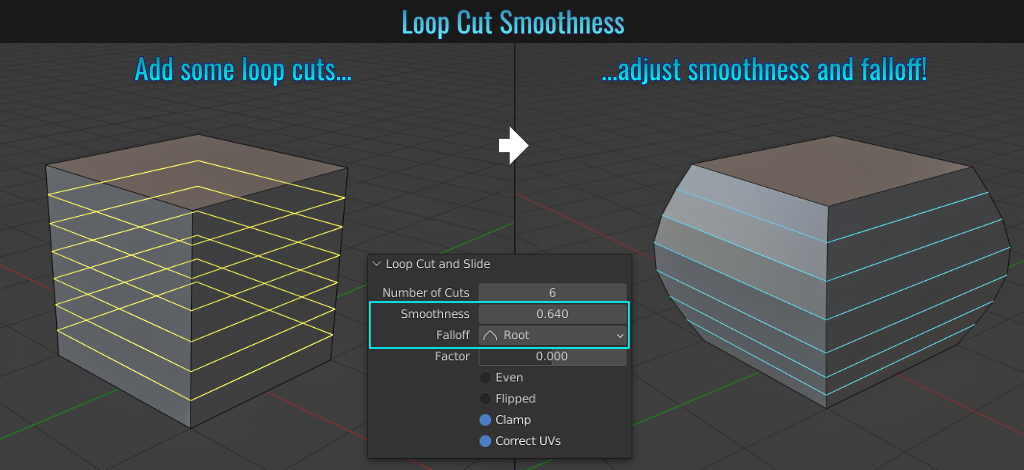
- Mesh bounding Box
It is easy to display a mesh bounding box by simply going into the Object Properties tab and from within the Viewport Display panel, enabling the Bounds option! There is also a Display Bounds Type drop down list where you can choose from different bound type options (Box, Sphere, Cylinder, Cone and Capsule!)
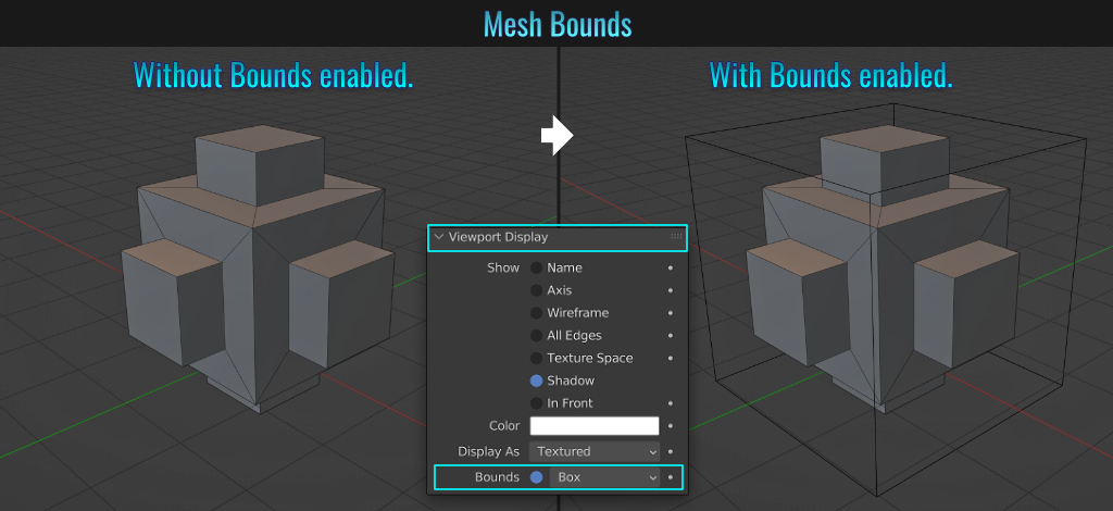
- Mirror Material
Mirror Mirror on the wall, which monkey head is the prettiest of them all? Creating a mirror is very simple! Ensure the rendering engine is set to Cycles and simply add a Glossy BSDF material with the Roughness setting of zero to whatever mesh you wish to make into a mirror (in this case, a plane that is set within a frame).
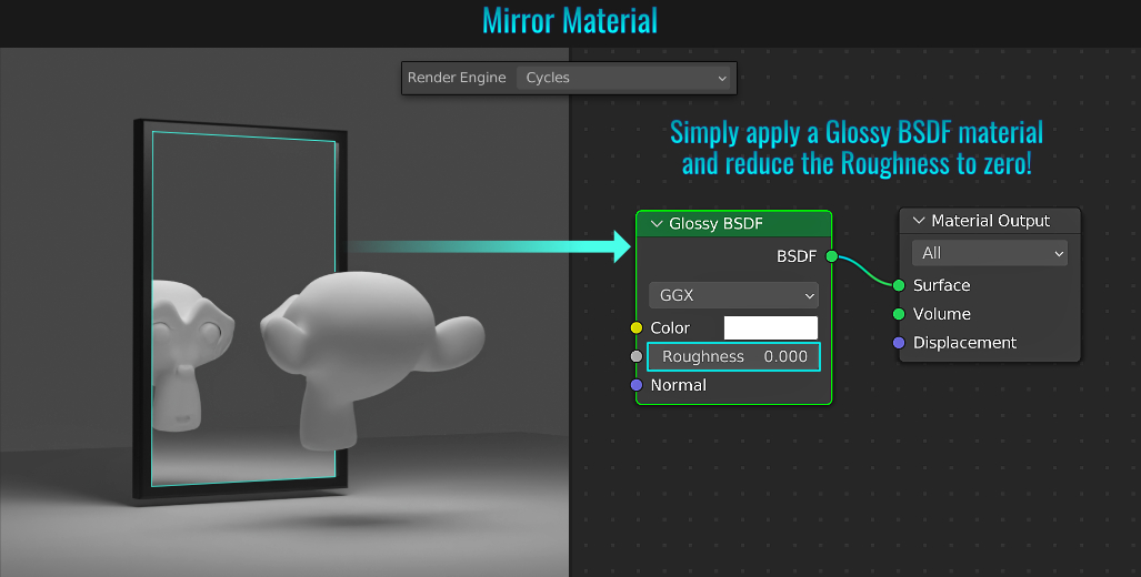
- Remove Unused Material Slots
It's not uncommon to start building up a bunch of mesh material slots. With this comes the possibility that some slots may end up not being used. Blender offers a way to clean this up by simply going to Material Specials dropdown arrow and choosing Remove Unused Slots. Only slots that are currently used remains! This is done on a mesh per mesh basis.
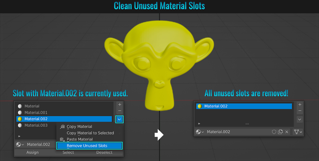
- Node Toggle Options
We know that shader graphs can become quite complex! Luckily, Blender has some node toggling functionality that can reduce the visual clutter in a manner that makes reading the graphs easier. For the sake of simplicity, the following example is nothing complex, but still illustrates the points this tip offers!
For each example, only nodes that are selected are affected! So without further ado, from within the Shader Editor menu:
Input/Output Visibility
Choose Node > Toggle Hidden Node Sockets (or Ctrl + H) and notice that all unused node inputs and outputs vanish, leaving only used ones visible!
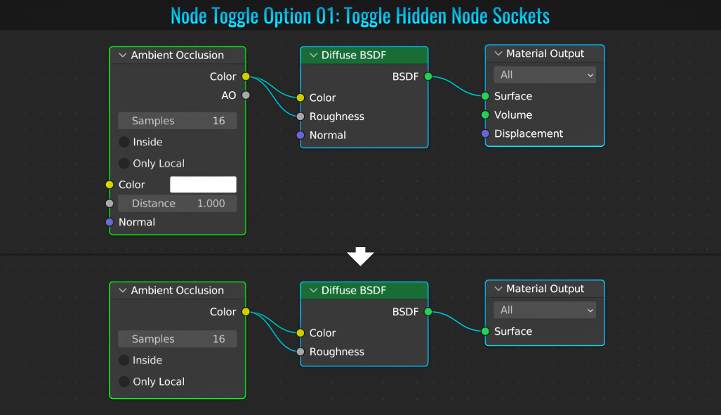
Options Visibility
Choose Node > Toggle Node Options and all checkboxes, input fields and dropdown menus are hidden!
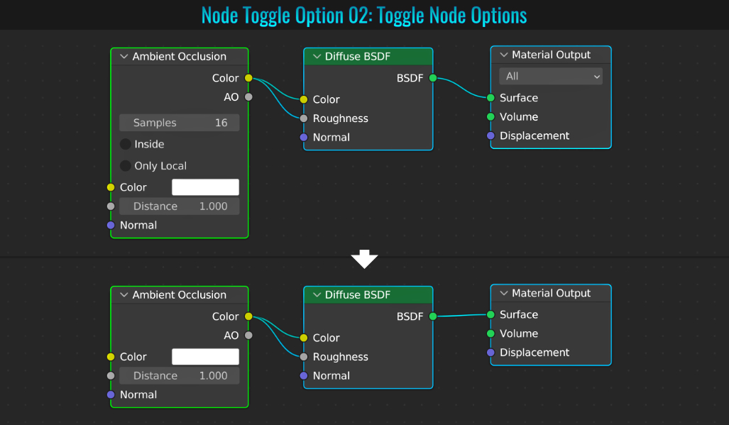
Socket Visibility
Choose Node > Collapse and Hide Unused Sockets and all checkboxes, sliders, dropdown menus and the like are hidden!
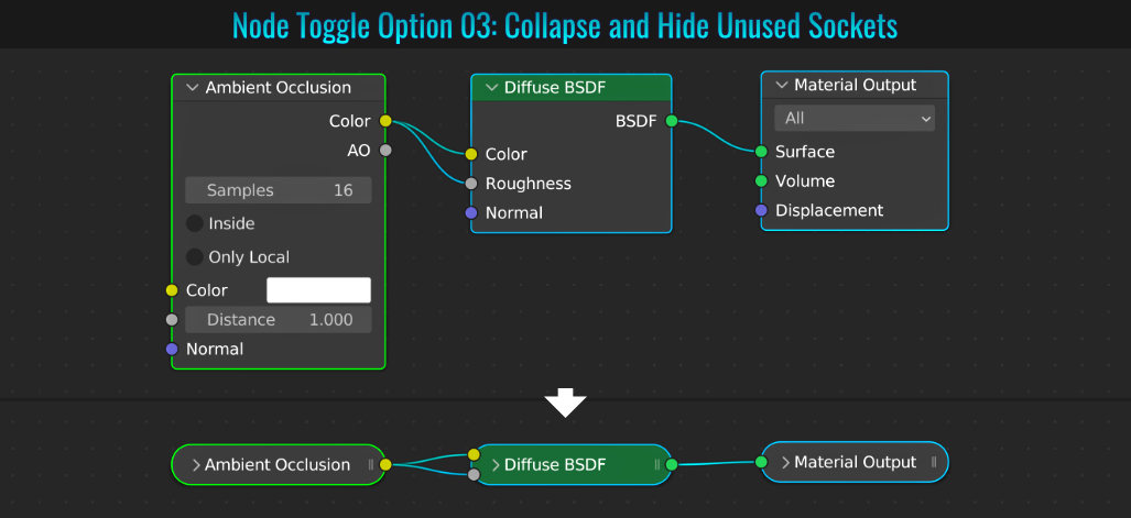
- Quick Wireframe
While with the mesh selected you can add a Wireframe modifier to convert your mesh into a 3d wireframe, another (albeit destructive modelling) way is to go into Edit Mode, select all the mesh faces and from within the 3d viewport menu, choose Face > Wireframe. This will pretty much do the same thing. Use the property panel in the lower left hand side in the viewport to play with Thickness and Offset values among others to dial in the wireframe look you going for!
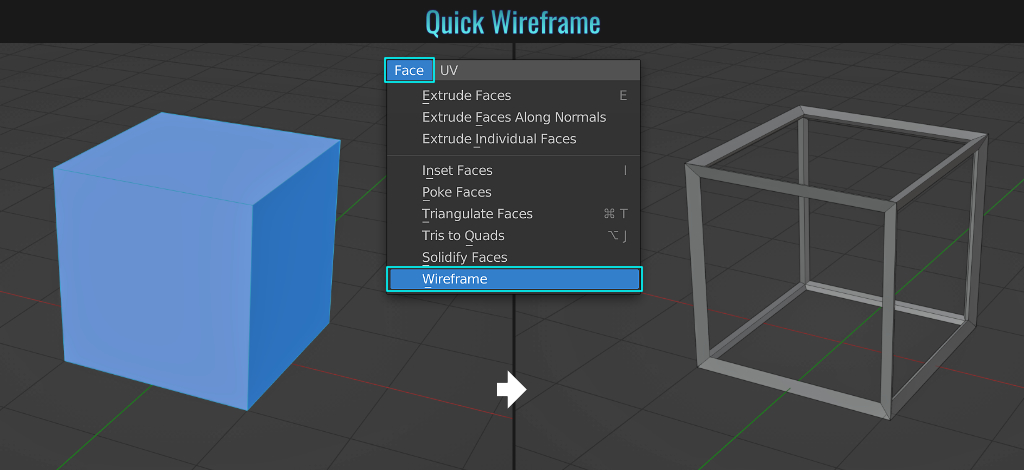
- UV Image Bounds
It is possible to prevent UV shells (islands) from leaving the UV space (be it by moving or scaling - rotations are not restricted) by going into the UV menu within the UV Editor and choosing Constraint To Image Bounds.
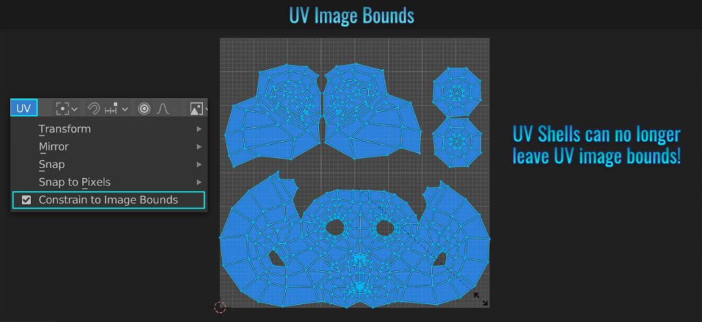
- Adjust Matcap World Space Lighting
With the viewport shading mode set to solid, the viewport MatCap lighting can be flipped by going into the viewport shading drop down menu and clicking on the small double arrow button. This will switch the matcap from left to right! Additionally, if the viewport shading is using Studio (instead of Matcap), you can enable the World Space Lighting icon and adjust the studio light rotation value to shift this lighting around!
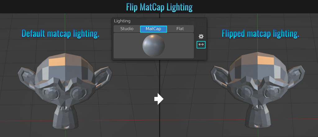
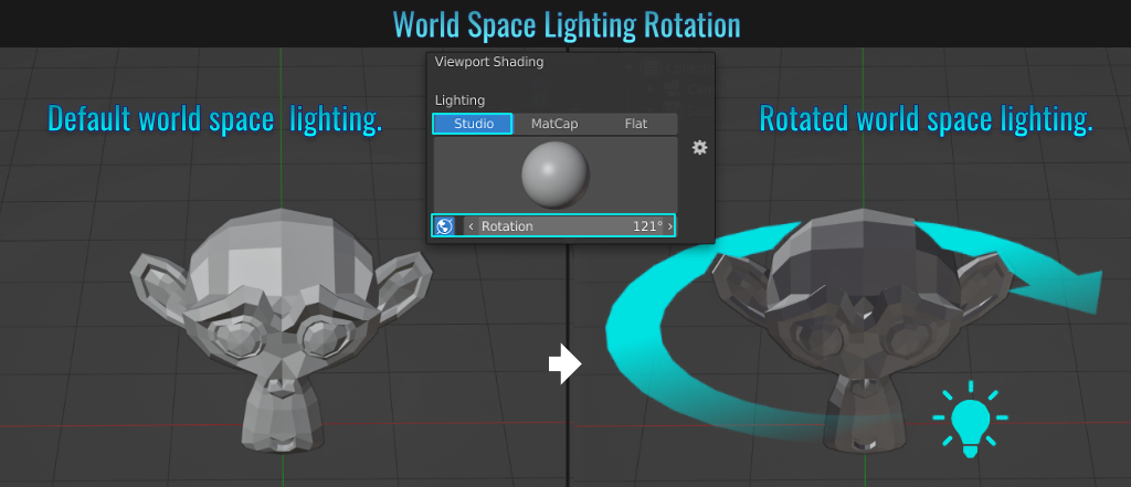
- Selecting Ungrouped Vertices
Sometimes it might come in handy to know which vertices are not part of a vertex group! In this example, the bottom half of the sphere's vertices are part of a vertex group. In Edit Mode, choose Select > Select All By Trait > Ungrouped Vertices. No more guessing which ones are not grouped anymore!
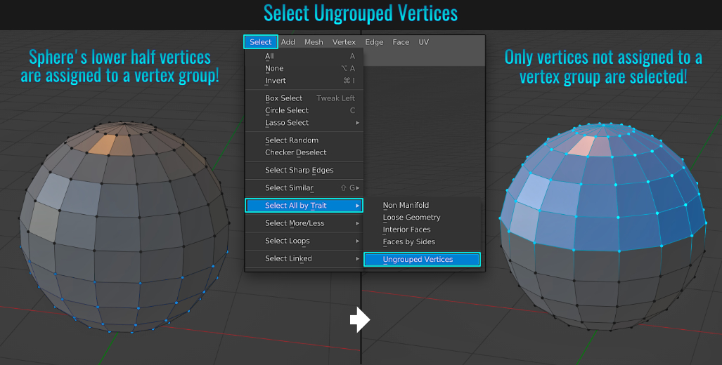
Within the Properties Editor tabs (think Object Properties, Object Data Properties, Material Properties, etc...) you can rearrange panels around, changing their order! Simply click on the tail end of a panel (which contains two little rows of four dots each) and drag to reposition it!
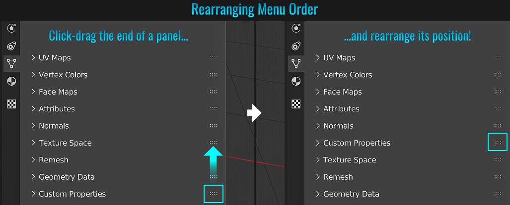
- Floor Constraint
In some cases when dealing with environment modelling, it would be great to be able to constrain meshes to a floor for example. To do this, start by selecting the prop in question (ensuring that its origin point is along its bottom), and from within the Object Constraint Properties
tab, choose Floor from the Add Object Constraint drop down menu!
Once the constraint is added, choose the ground / floor mesh from the Target field! Now, the prop will not be able to pass through the floor mesh anymore. Furthermore, moving the
ground up will result in the prop following along!
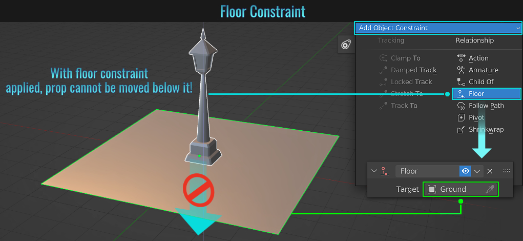
- Quickly Find Object In Outliner
First, select a mesh in the 3d viewport. Then simply hover the mouse cursor over the Outliner and press . (period on the Numpad) and voila! Selected mesh is selected in the list!
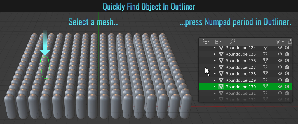
Sometimes either a camera or the viewport view will clip geometry. This has everything to do with Clip Start and End settings!
Camera Clipping
To see how much the camera can see, select the camera and from within the Object Data Properties tab (the one with the camera icon) enable Show • Limits from the Viewport Display panel! The Clip Start and End range is indicated
as a line with a start and end point. Any objects that fall within these are visible to the camera. To change this range, simply adjust the Clip Start and End values from within the Lens panel!
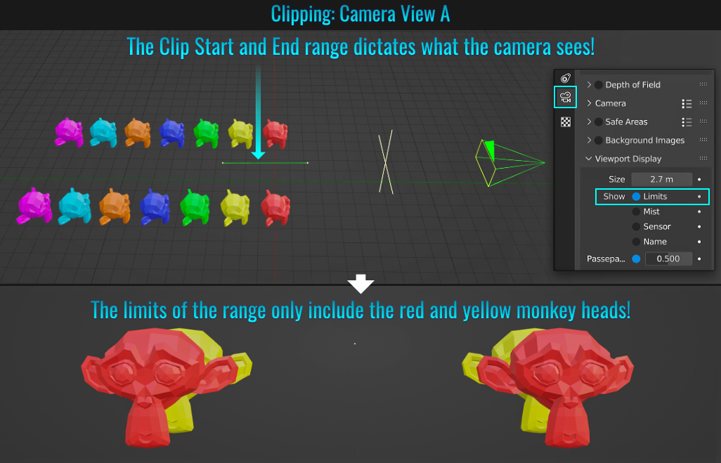
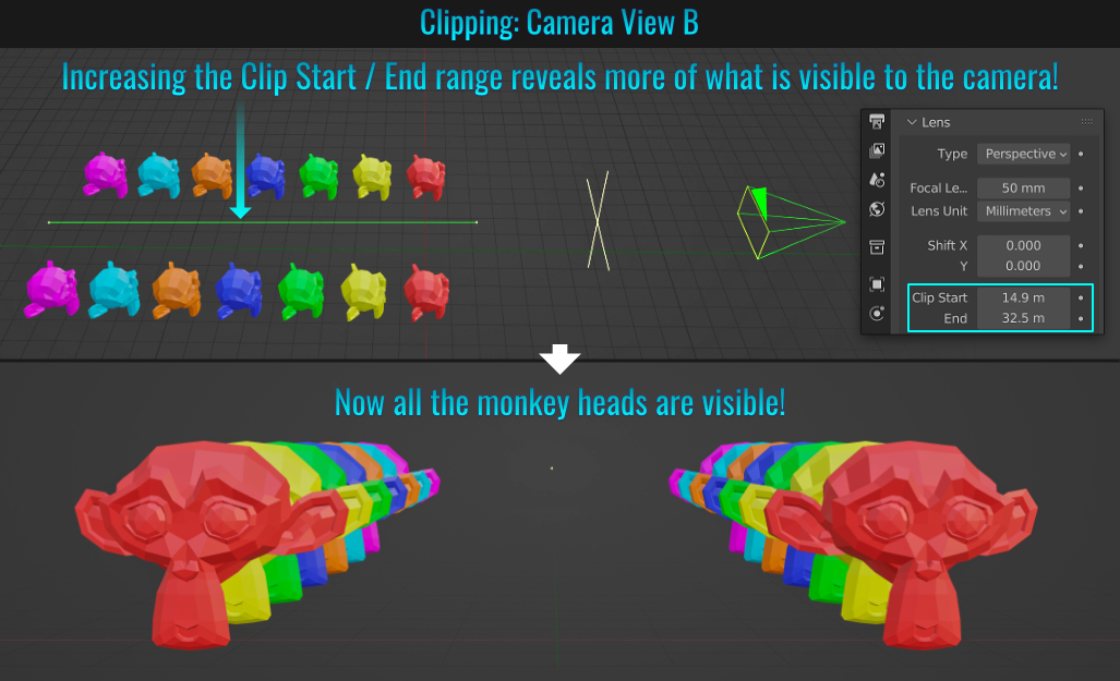
Viewport Clipping
Using the red monkey head as an example, it is clipped with the view being so close! To fix this, simply press N to bring up the right-hand side bar and from within the View tab, adjust the Clip Start and/or End settings to
reveal the entirety of the mesh(es) in question!
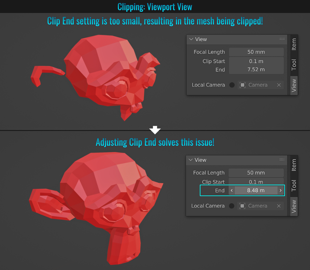
Side Note: Reducing the Clip Start value to as low as possible and cranking the End setting to be very large can have detrimental geometric rendering results in the 3d viewport! Keeping the Start and End values within a reasonable range will render geometry correctly!
- Incrementing Files
When saving files, you can easily make use of file incrementalism in the event you want to create different file versions. This can be done in one of a few ways:
- Click on the Plus or Minus buttons on the far right side of the file name text field (which will increase/decrease version numbers by 1)
- - or -
- With the mouse cursor hovering over the file name text field, press Numpad + or Numpad - to increase or decrease the file name version number (by counts of 1) respectively! Additionally, doing so while pressing Shift will increase or decrease by counts of 10 while pressing Ctrl will be affected by a factor of 100!
Sometimes it might be more helpful to have meshes and/or wire frames with different colours in the 3d viewport to better differentiate between them! The process is relatively easy too!
Random Mesh Colours
With the Viewport Shading mode set to Solid, ensure that the Color section is set to Random!
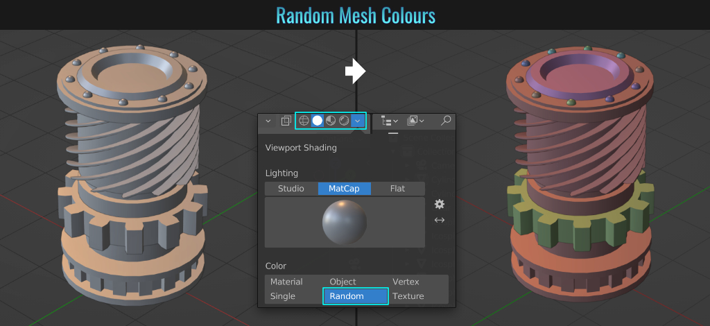
Random Wireframe Colours
With the Viewport Shading mode set to Wireframe, ensure that the Color section is set to Random!
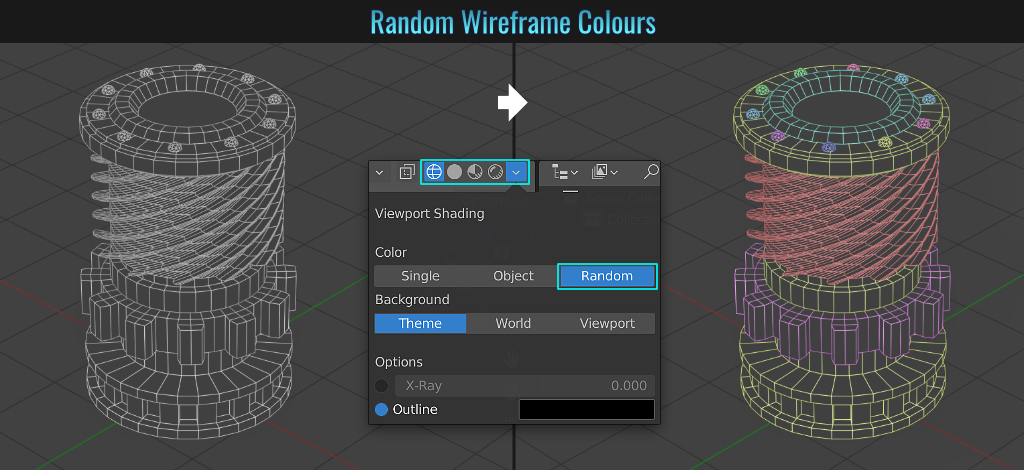
- Memory Undo Limit
If you find that the current number of undos isn't enough, you can easily change this by going into File > Preferences and from within the System section on the left hand side, adjust the Undo Steps value in the Memory & Limits area.
Just be careful not to crank this value too high, as this can result in excessive memory usage, something that isn't desirable. If you start feeling the need to go really high, this might be an indication for the need to perhaps do incremental saves instead?
(see tip Incrementing Files)
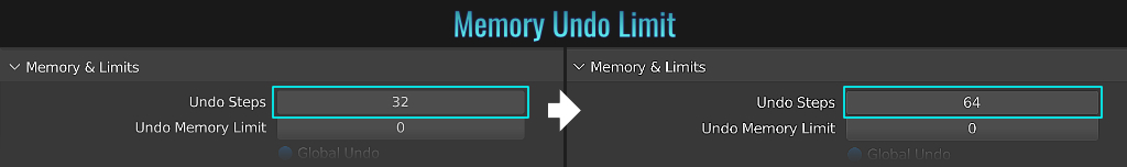
- Holdout Collection Masking
It's possible to use geometry for the purpose of transparent masking (be it in the 3d viewport or for rendering)! Start by selecting geometry for masking purposes, press M, choose + New Collection (as this masking technique requires a dedicated collection to work) and give it a relevant name. In the Outliner, from the Filter menu, enable the Holdout option. Ensure that the masked collection has this filter enabled. Finally, to see the transparency affect, go into the Render Properties and from within the Film panel, simply enable the Transparent option!
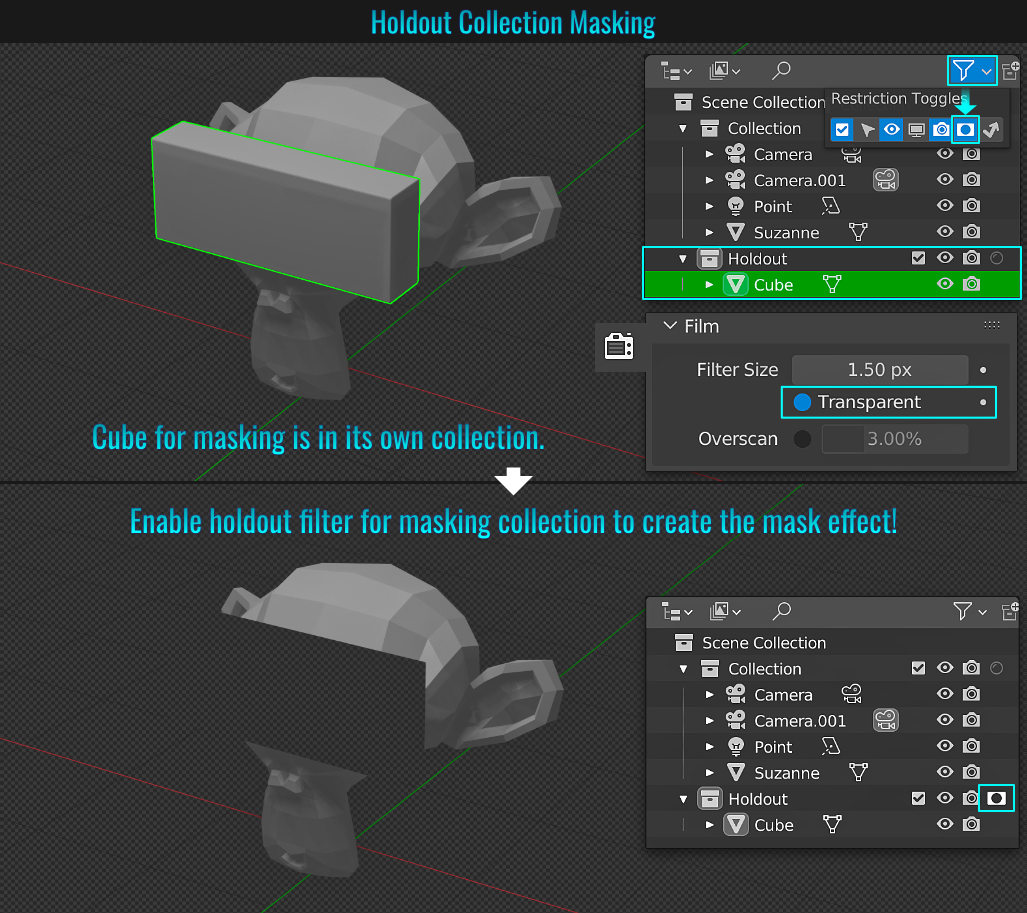
Area Options
With regards to splitting a viewport, while you could place your cursor over a viewport corner (the cursor turns into a + symbol) and drag either across or down to create a new viewport horizontally or vertically, did you know you can also do so by hovering your cursor over the viewport bottom border (the cursor turns into an up/down arrow separated by a bar in the middle), right click and choose between horizontal or vertical and mouse clicking in the viewport to determine the split? Holding Ctrl after commencing the split snaps the split in increments!
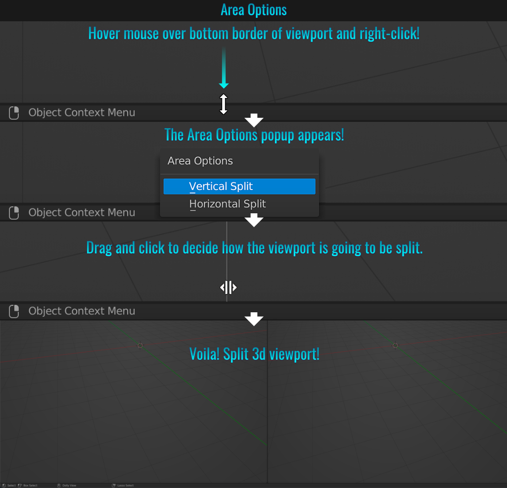
Status Bar
Moving the mouse cursor even further down below the bottom border of the 3d viewport (the cursor becomes an arrow) and right-clicking will bring up the Status Bar where you can enable things like which version of Blender is being used as well as things like Scene Statistics, System Memory and Video Memory!

- Bevel Clamp Overlap
When beveling multiple edge loops simultaneously, their heights are not restricted, leading to potential overlaps! But while the bevel tool is active, pressing C while dragging multi-bevels will clamp each as they collide with one another!
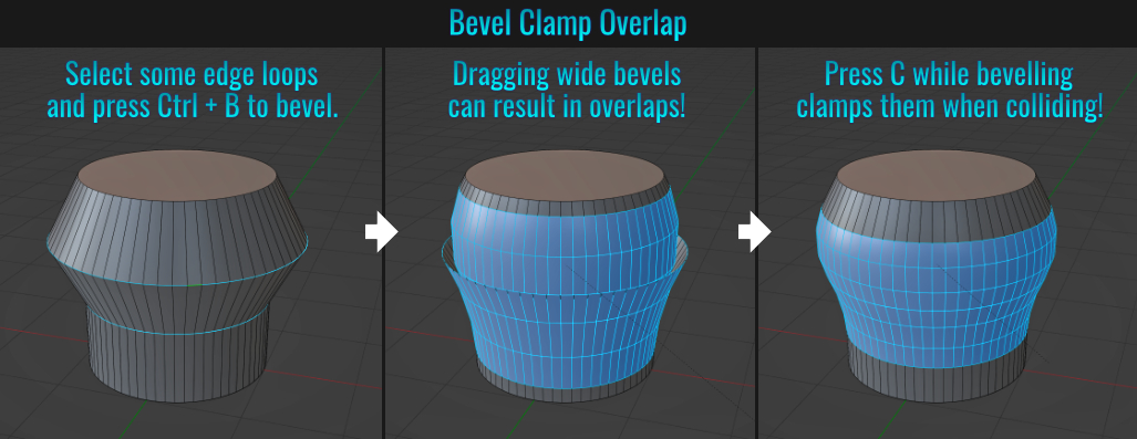
Note: With clamping, vertices that 'collide' will not merge, even with Auto Merge enabled!
This is due to the fact that there is face(s) between these vertices.
Add a camera and frame your mesh (as a camera is needed for this to work). Press Shift + A (to bring up the Add menu) and choose Grease Pencil > Stroke. This will add a grease pencil stroke in the viewport. Move this out of the camera's view, and then
first select your framed mesh, then Shift + click the stroke and from the Modifier tab, choose Line Art.
From here, choose either a collection or mesh to be affected, then the type of Layer (Colors or Lines) and finally the colour itself!
This stroke affect can be tweaked by playing various modifier settings as well as settings found in the Object Data properties tab (the icon looks like a swirly line with rectangular end points).
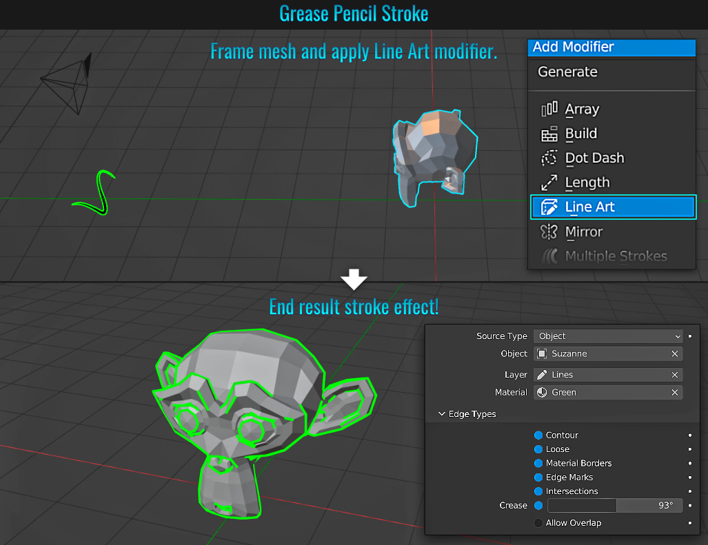
While you can only select and use one rendering engine at a time, it's possible to have two 3d viewports, each displaying the scene in Eevee and Cycles respectively and simultaneously!
Step 1: Set rendering engine
From within the Render Properties tab, set the rendering engine to Cycles.
Step 2: Add a camera
Add a camera to the scene and frame your object(s). Then press N to bring in the side bar and enable Camera to View in the View Lock panel.
Step 3: Viewport split and settings
Split your current scene into two 3d viewports (see tip Area Options & Status Bar). In each viewport, go into the Viewport Shading drop down menu along the top and ensure that Scene Lights, Scene World / HDRI material sphere have identical settings if you want the most evenly comparable results! Set one viewport's shading mode to Material Preview (this will act as the Eevee viewport) and the other viewport to Rendered (this one is Cycles). Voila! You now see the scene in both engines (kind of)!
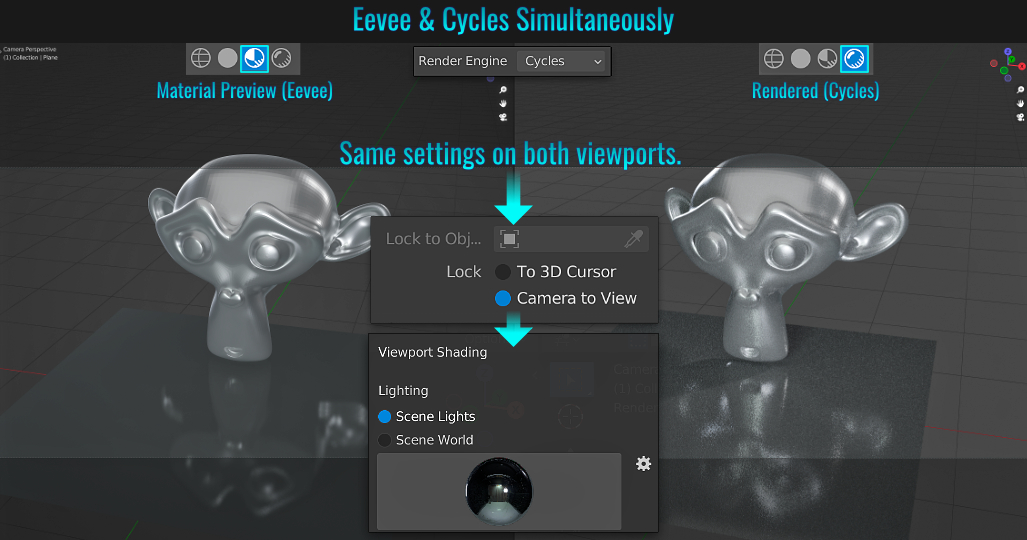
- Node Selections
Here is a small collection of nice-to-know node selection tips:
- Press A to select all nodes.
- If one or more nodes are selected, quickly double tap A to deselect all.
- With a node or more selected, press Ctrl + I to invert the selection.
- With a node selected, press L to select Linked From.
- With a node selected, press Ctrl + L to select Linked To.
- If there is a group, press Shift + G to select group.
- Press Shift + [ or ] to select another node of the same type.
- Press Ctrl + F to find a specific node.
- With one or more nodes selected, hold Shift + LMB on another node to add it to the current selection.
- Billboard & Camera Constraints
A billboard is basically a plane that always faces the camera. So this tip will kill two birds with one stone. We'll look at a plane (acting as the billboard) and in turn the camera will always look at the plane! Let's use the following example to illustrate how this all works!
Make a plane as a billboard
The plane has been rotated so it is upright with its rotation transform applied (Ctrl + A > Rotation). With it selected, go into the Object Constraint properties tab and choose Locked Track. Set the Target field to be the camera. In this case, the Track Axis is set to -X while the Locked Axis is set to Z. Your situation may differ, but this is a common setup.
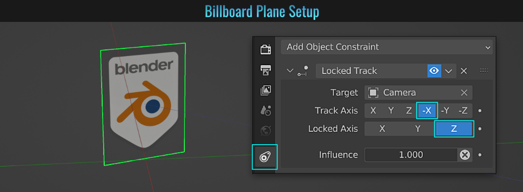
Make the camera always look at plane
With the camera selected, go into the Object Constraint properties tab and choose Track To. Within this constraint, set the Target to be the plane. Set the Track Axis to -Z while the Up value to Y.
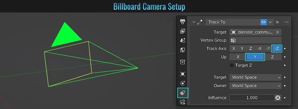
Now, when the camera is moved in the 3d viewport, it not only locks onto the target plane, but in return, the plane acts as a constantly camera-facing billboard! Of course, settings might need to be adjusted differently depending on your scene.
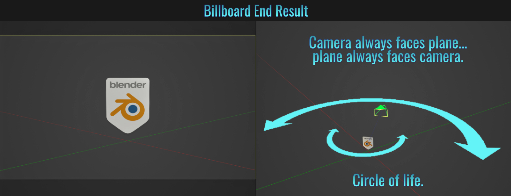
- Select All Objects In A Collection
Blender allows us to group objects into collections (you can think of these as being similar to "folders").Start by selecting all objects and putting them into a collection (Press M New Collection). Now with one of the meshes selected, let's see the various
methods of selecting all meshes:
Method 1: Adding To Favorites
Press Shift + G (to bring up the Select Grouped menu), right-click on Collection and choose Add to Favorites!
From now on, you can access this by pressing Q and selecting the Collection item from your favorites list!
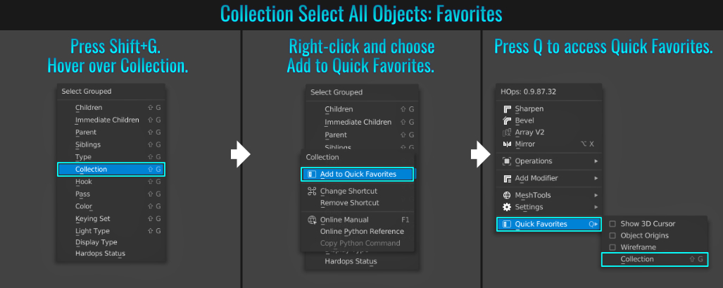
Method 2: Selecting Objects Via Outliner
You can right-click on the collection itself in the Outliner and choose Select Objects.
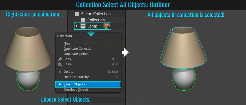
Method 3: Setting A Keyboard Shortcut
- Go into Edit > Preferences and from within the Keymap panel, open the 3D View collapsible menu. Then open the nested Object Mode menu, and then the sub-nested Object Mode (Global) menu.
- Scroll all the way to the bottom of this section and click on the + Add New button. This will create a new shortcut entry (titled "none")!
- Open this entry, and in the "none" text field, replace the text with object.select_grouped and hit Enter! The contents will be updated with the select group info!
- Change the actual keystrokes needed to execute this command! In this example, the shortcut was set with the Press dropdown menu to Double Click and the actual keystroke field (which defaults to "A") to be Left (by left clicking it). Of course, this is subjective. Feel free to choose what works best for you!
- From the Type dropdown menu, choose Collection. Don't forget to save your preferences afterwards!
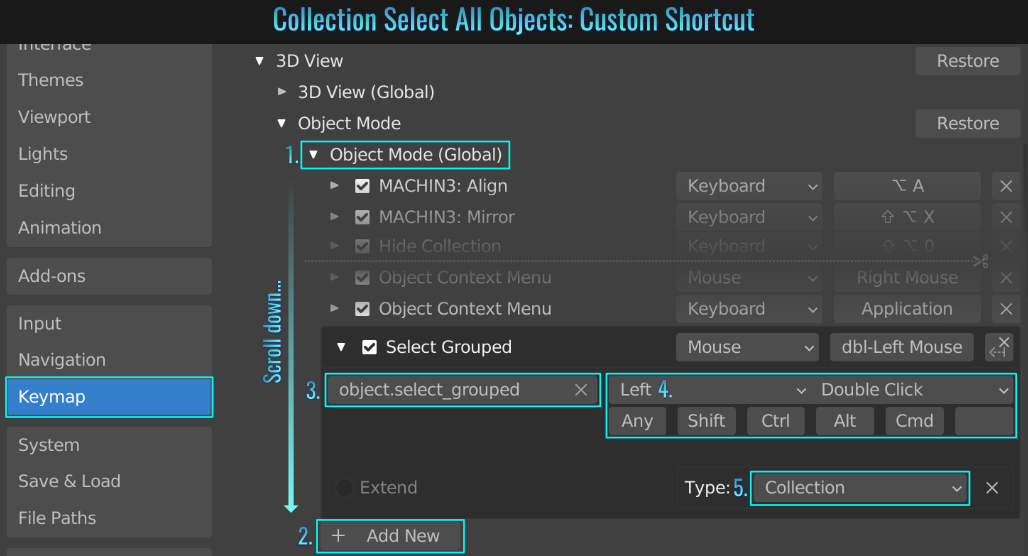
- Procedural Curvature Effect
While there is no dedicated curvature node in Blender, there is a way to set this up in the Shader Editor to achieve the curvature effect! This is useful for baking worn edges! For starters, from within the Render Properties tab, set the Render Engine to
Cycles. With a material applied to your mesh, go into the shader editor and setup everything using the accompanying screenshot as reference. A few things to note:
- Multiply node: This is simply a Math node set to Multiply, which acts as the curvature spread!
- Dot Product node: This is basically a Vector Math node set to Dot Product. In layman's terms, a dot product basically calculates the angle between two vectors!
- Map Range node: This takes the end result from the Dot Product and remaps the value from a range to a target range. Playing with this node's values can alter the darkness/lightness and contrast of the overall curvature effect! Invert the To Min and To Max values!
- Optionally, you could plug a Noise Texture into the Multiply math node to generate random wear and tear within the curvature effect.
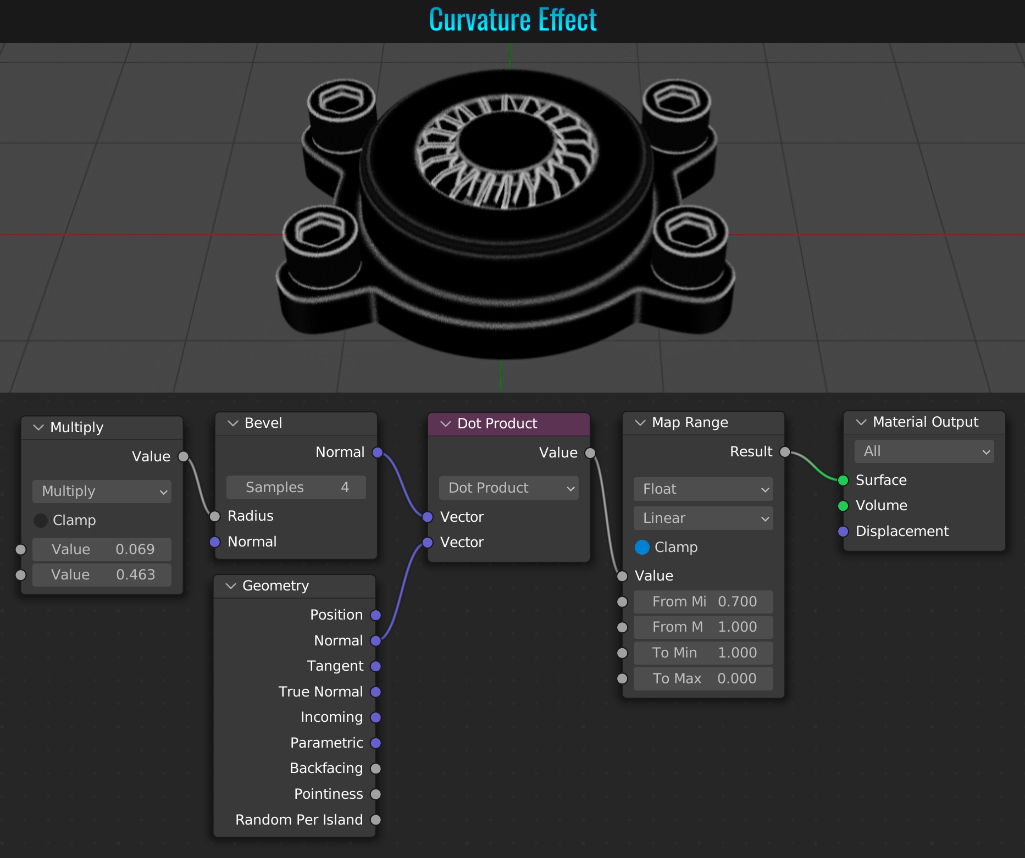
- Aiming Directional Lights
Blender offers a few ways of changing the direction of a light. In this case, the light refers to a directional one (i.e. Sun, Spot or Area). Let's examine how this can be achieved.
Align Light To View
This info is similar to tip# 56: Adjusting View Through Camera / Light, but offers yet a different approach in this bundled tip! Frame the mesh(es) in the view and with a directional light selected, press Control + Alt +
Numpad 0. The light will now align with the view!
Align View To Light
Optionally (but less favorable), with the light selected, press Ctrl + Numpad 0 (this will align the view to the light)! Then double tap R to freely rotate the light to frame the mesh(es) in question (this is more cumbersome in getting a quick
accurate view however)!
Use Directional Control Point
Every directional light in Blender comes equipped with a directional control point (for the lack of a better term). This is represented by a small yellow dot along the light's line that represents its angle in the 3d viewport. Simply click-drag this point to change the light's direction!
Track Mouse Movement
With a light selected, press Shift + T, then move the mouse around. The light will rotate, constantly aiming towards your mouse cursor until you left-click to finalize the operation!
- Show Complete Subdivision In Wireframe
When a subdivision modifier is applied to a mesh and is viewed in wireframe mode (press Z and choose Wireframe), the subdivision is "optimally" displayed. Basically, Blender is showcasing a simplified version of the wireframe. If you uncheck the optimal display option from the modifier panel however, the subdivision mesh will be displayed in all its dense wireframe glory!
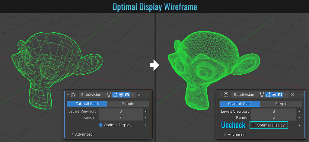
- Distribute Gradient Stops Evenly
When inserting gradient stops, it's easy to evenly space them out by simply clicking on the ColorRamp's dropdown arrow and choosing Distribute Stops Evenly!
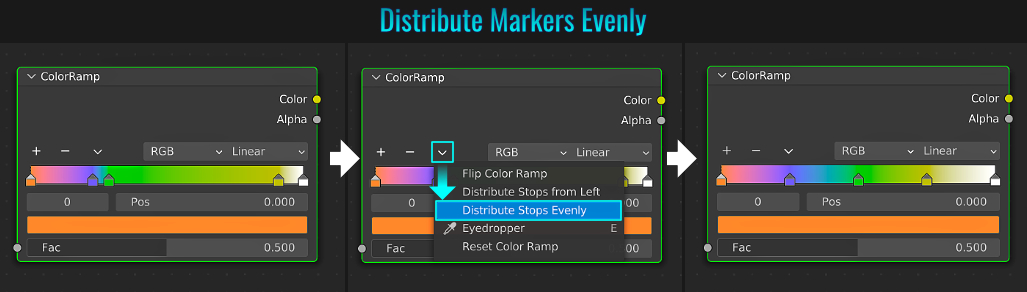
Blender is very customizable, allowing us to change many visual aspects. Whether it's weakening eye sight or simply a preference, among them is the ability to change the size of vertices within the 3d viewport! To change this, simply go to Edit > Preferences and from within the Themes side panel, open up the 3D Viewport dropdown and scroll all the way to the bottom until you see the Vertex Size option. Play with this to increase or decrease the size of the vertices as you see fit!
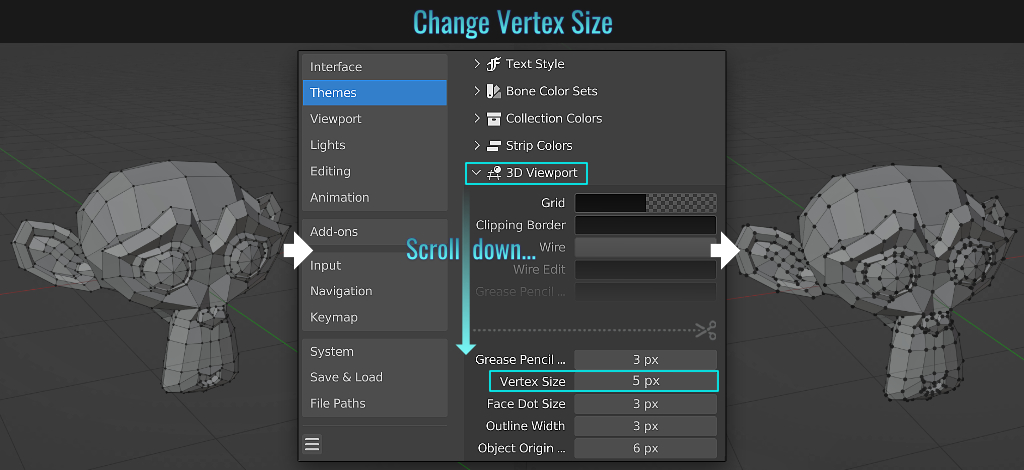
- Camera Depth Of Field & Adjustments
Setting up the camera's depth of field is pretty easy in Blender. Simply start by selecting the camera in question and from within the Object Data Properties tab (the one with the camera icon), enable the Depth Of Field option. Next, from within the
Viewport Display section, enable Limits!
At this point, you'll notice a straight line projecting from the camera and a cross hair placed along it. This is the focal point. This can be manually positioned along the camera line by adjusting the
Distance value found within the Viewport Display section. But you can force the camera to focus on a specific mesh by either using the eye dropper or dropdown list from the Focus Object field! Adjust the F-Stop value within the Aperture
section to really dial in how out of focus the background becomes!
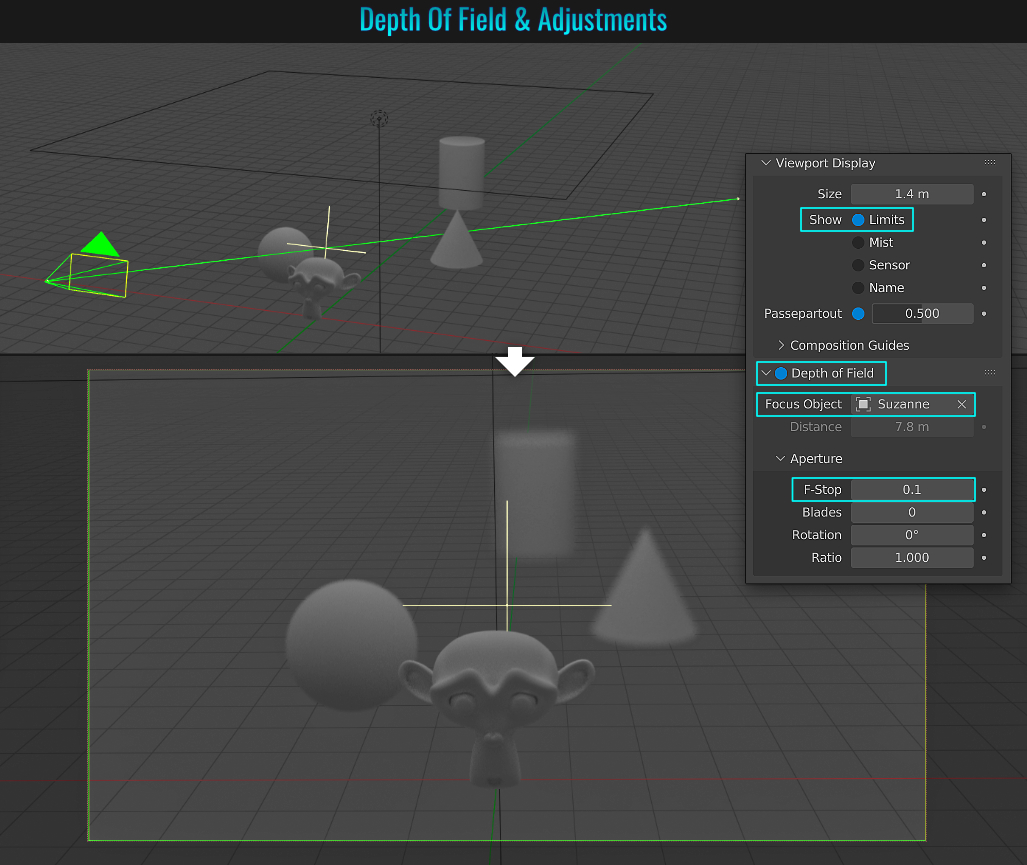
- Customize Color Picker
You can choose between different color pickers by going to Edit > Preferences and from within the Interface panel, there is a dropdown menu option called Color Picker Type in the Editors section. Choose between Circle or Square types along with a mode (Hue, Saturation, Value etc...)
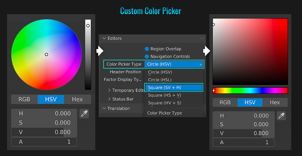
- Deleting Collection hierarchies
Ever try deleting an entire collection and everything in it by simply selecting the collection in question and pressing X, only to see the collection itself disappear but the objects within it remain in the Outliner? Frustrating, isn't it? Below are two different methods
of removing the collection with everything in it (which involves deleting hierarchies!)
Method 1: Right-Click Delete Hierarchy
From within the Outliner, right-click on the collection in question and choose Delete Hierarchy! Poof! Everything inside the collection as well as the collection itself is completely removed!
Method 2: Enable Delete Hierarchy Shortcut
This is the more preferable method! Go to Edit > Preferences and from within the Keymap section on the left hand side, type delete in the search field. Scroll down until you find the Outliner category and open up the delete shortcut that is pointing
to the X key. Notice at the bottom of this shortcut there is an unchecked Hierarchy radial button? Simply enable it and save your preferences! From now on, whenever you select a collection in the Outliner and press X, it is removed along with all objects within it!
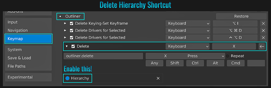
- Curve Pen Tool Improvements
The following is for Blender 3.2+ only! The Curve Tool has be overhauled to behave much more like the pen tool in Photoshop or Illustrator! We'll start with a single curve point. Starting with a single point isn't necessary, but makes for a cleaner start!
Begin by pressing A (to bring up the Add popup) and choose Curve > Point (you'll need to install the already included Add curve: Extra Objects add-on for this).
In the Simple Curve operator popup in the lower left-hand side
of the 3d viewport, ensure that 3D is selected (2D is the default) and that the Output Curve Type is set to Bezier (assuming this is the type of curve you would like to work with) as well as choosing Vector.
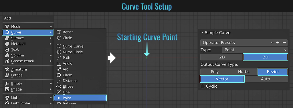
With the single curve point selected in Edit Mode and the Curve Pen tool selected (left-side tool menu - if it's not visible, press T in the viewport), below are the following mouse clicks and drag behaviours that affect the new Curve Pen tool's capabilities:
- Simply clicking somewhere in the viewport extends the curve to another curve point that is a vector type, which is considered like a "hard corner" type! This is great for angular curves!
- Click-dragging somewhere adds a new point, but the new curve segment becomes more curved the more you drag the mouse cursor! This comes in handy for creating pipes or a profile of a wine glass for example!
- Multiple uses with the Ctrl key:
- Holding down Ctrl and left clicking on a curve segment inserts a new curve point for further curve refinements!
- Ctrl and clicking on an existing point removes it!
- Finally, left clicking a new point and pausing (continue holding down mouse button), holding Ctrl and then dragging will alter this newest curve segment's curvature!
- Left click-dragging somewhere and then holding Shift while dragging will break the the outgoing bézier handle tangent, allowing you to create a "hard corner". This allows for creating a mix of smooth and harder curves! You can even change the tangent of one of the handles of an already established point by selected a curve point, then left click-drag one of its handle control points and start to drag, pause, hold Shift then resume dragging!
- Click-dragging a curve segment (or even a point) alters its curvature. This is useful for tweaking a portion of the curve!
- To constrain drag one of the bézier handles (along its axis) while not altering the other side, start click dragging just to get started and pause (don't release mouse button), then hold Alt and continue dragging! This will ensure the other handle's tangent is unaffected!
- Hold Shift and click multiple curve points to move them simultaneously.
- Select two open curve points and press F to close the curve!
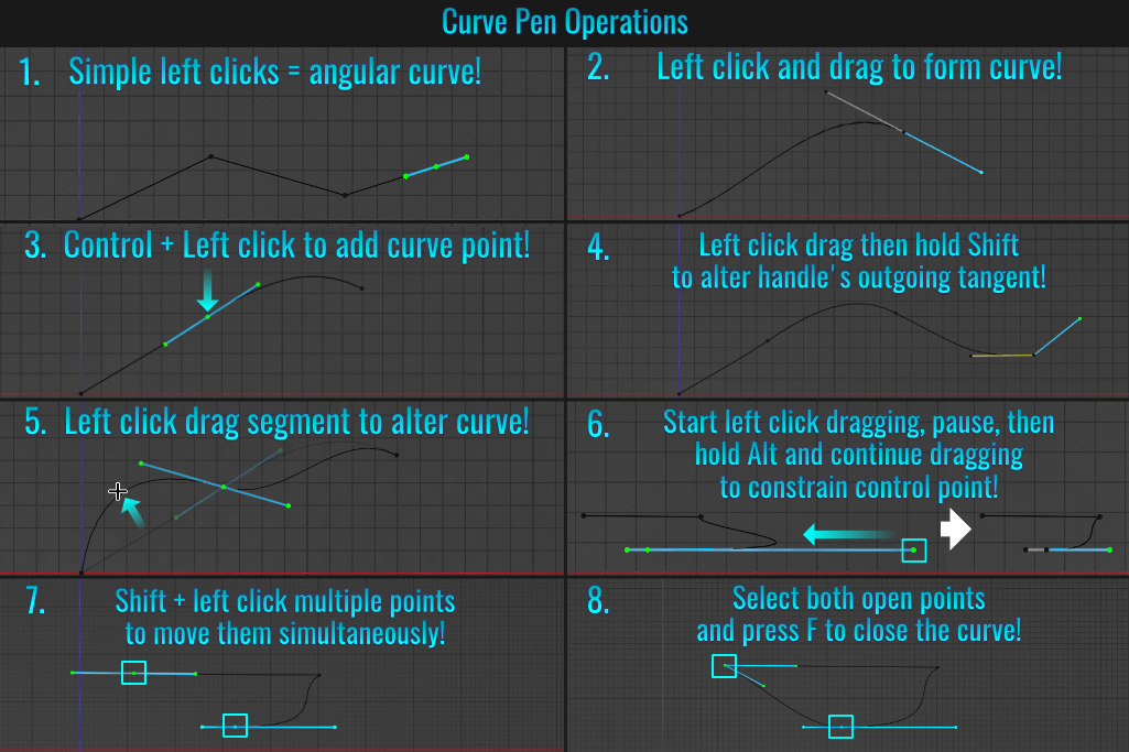
You can read more about curves in Blender's Curve Pen Documentation.
- UI Value Adjustments
Aside from the usual click dragging or clicking on side arrows to change a numerical text value (like those found in shader nodes, transform panels, etc...), here are some additional ways of adjusting them:
Fine-tune Using Shift Key
When you start click-dragging on a field's value, it can adjust quickly (sometimes too quickly)! But if you hold down Shift while dragging, the values adjust much slower, allowing you to fine tune things!
Mouse Wheel Scrolling Using Control Key
It is also possible to hold Ctrl and middle mouse scroll while hovering over a value! This also acts as a fine-tuning of sorts!
Snap Dragging
While click dragging a value, holding Ctrl will jump the value up/down in increments!
Beyond Slider Limits
Some sliders have soft limits, meaning there is a capped default range (from say 1% to 100%). You can go beyond this limit by simply typing a value that is less or greater than this default range! In essence, you are creating new hard limits.
Cancelling An Adjustment
While click dragging a value, if you decide to cancel this adjustment, simply right click! The initial value will be instantly restored!
Toggle Positive / Negative Values
Simply hover over a value and press - (not on the numpad) to toggle it between being positive or negative! Values of zero will not change for obvious reasons!
Adjust Multi Values Simultaneously
To adjust two or more vertically stacked consecutive text field values at once, simply click and drag vertically from the first field to the last one. While still holding down the left mouse button, dragging left/right will cause all fields involved to adjust - or - release the mouse button,
type in the new value and hit Enter! All selected fields will now contain the newest value!
Reset Value To Default
Hover over a value and press Backspace to revert it back to its default setting! In the event of related fields (like Location X, Y and Z for instance), all field values will be reset!
Expressions And Units
It is possible to enter expressions into a numerical field! For example, say you had a field with a value of 5, and you needed this value to be divided by 3, you could simply change the field's value by typing 5/3 and hit Enter. In this case, a value of 1.667 would be returned! If you ever needed to deal with PI values, simply enter pi in the field and Blender will automatically interpret it as 3.14159°. Isn't expressions fun?!? Additionally, it is possible to mix related units within expressions, like entering 2ft/0.7km into the Location X transform field for example! The result of 0.870857 m is applied and the mesh will move this distance in X accordingly!
- Parent To Vertex
These tips and tricks don't include tutorials (as this is a future section), but to better illustrate this tip, we will walk through the process! While at first glance it seems strange to be able to have a child mesh parented to one or three vertices (no other amount will work)
of a parent mesh, it is beneficial in the event the parent mesh deforms while the rigid child mesh(es) move along with it (as though pinned). In this example, we'll use a cloth banner with rigid bird emblems attached to it!
Banner Setup
Start by making an elongated, multi segmented plane that is rotated 90 degrees and apply all transforms (by pressing Ctrl + A and choosing Apply All). In Edit Mode and with Vertex Mode, Select the two top end vertices and
assign them to a vertex group (see tip Vertex Grouping).
With the banner still selected, go to the Physics Properties tab, click on the Cloth button, and set the Vertex Mass value to something like
10 kg (feel free to experiment). Scroll down, open the Shapes panel and from Pin Group, select the vertex group we just created! Place the bird emblems (or whatever you wish) into the proper location on the banner. Repeat the
following for each bird emblem mesh (or whatever you mesh are using):
- Select the emblem, then Shift click the banner.
- Press Shift + Z (wireframe mode), then go into Edit Mode, and with Vertex Mode, select three vertices on the banner that is closest to the emblem mesh and press Ctrl + P. Click Make Vertex Parent from the resulting popup.
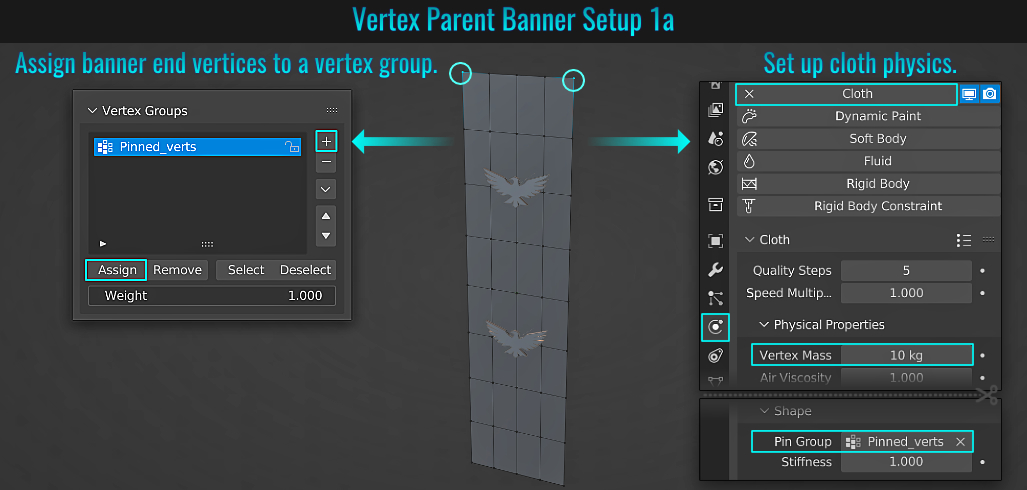
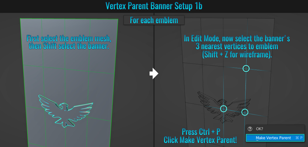
Finally, press A and choose Force Field > Wind. Rotate the wind so that it is facing the banner and set its strength to something like 100 (again, experiment). Play the simulation (depending on how your Blender app is configured, it might be the Space Bar or Shift + Space Bar). Notice that the bird emblem meshes move along with the deforming cloth banner in the wind!
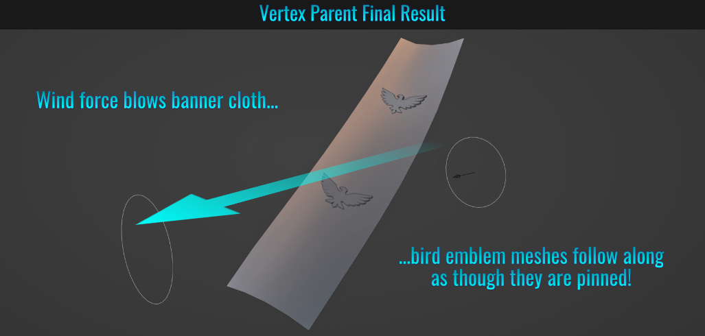
- Purge Orphan Data & Clean-Up
When working on Blender files, it is not uncommon for unused data-blocks pointing to meshes, materials, images and whatnot to start piling up. This can add unnecessary bloat to the file size!
To clean this up, go to the Outliner and switch its Display Mode to
Orphan Data (its icon truly is a heart breaker!) The Outliner will now list the applicable sections containing orphaned data. All that's left is to simply click on the Purge button found at the very top right hand side of the Outliner UI! All unused data-blocks that can be
purged will show up in a purge popup asking to click on it to proceed! You may proceed!
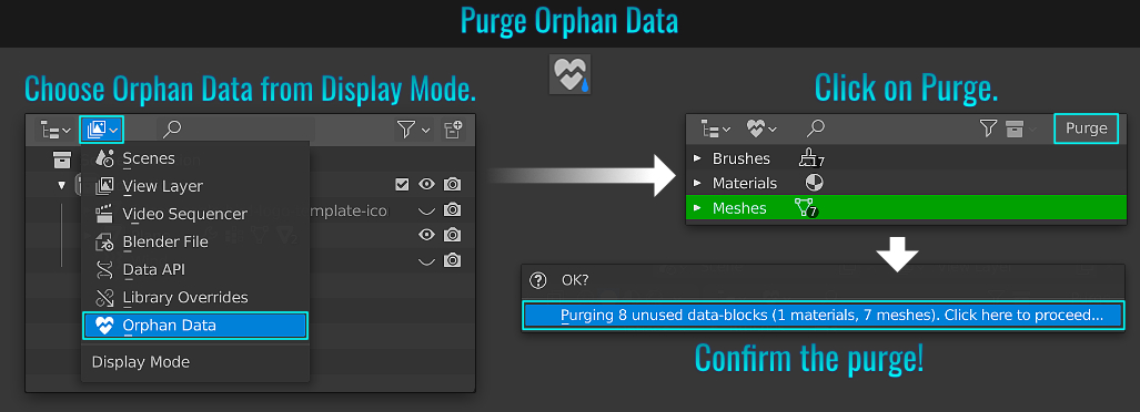
Additionally, you can clean up things by going to File > Clean Up where you will find a host of unused and recursive data-blocks, linked data-blocks and local data-blocks!
- Join Nodes With Node Wrangler
If you haven't already installed the included add-on Node Wrangler, you really should! It offers plenty of functionality (too much to go over here). But this tip involves quickly joining two nodes together. Simply hold Ctrl + Shift and right-click drag from one node to another! They will be joined automatically using the appropriate joining node!
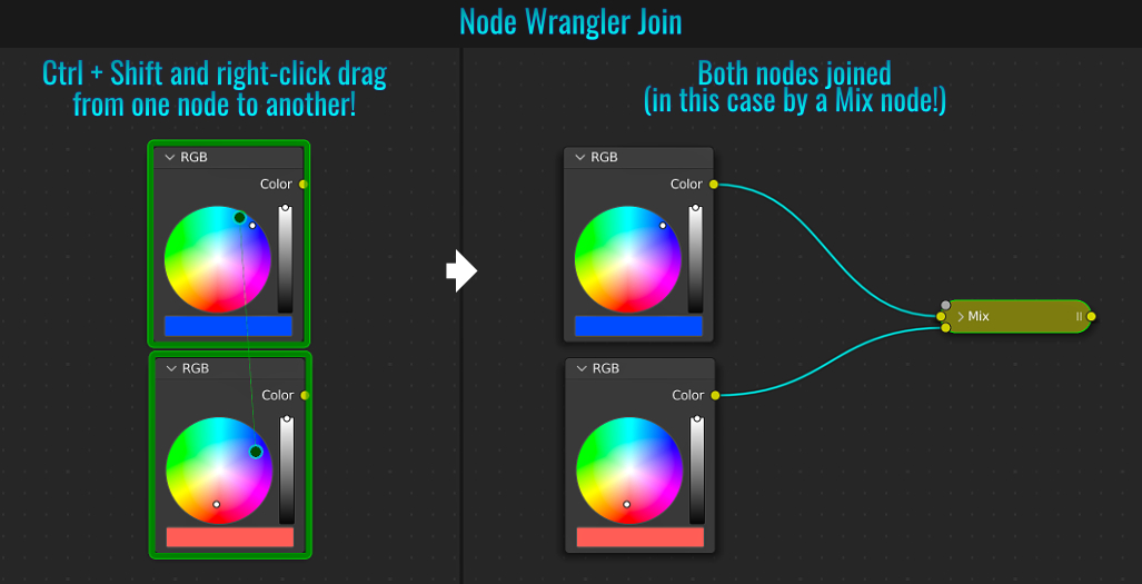
- Bevel Intersection Types
Normally, while performing a bevel operation (Ctrl + B) with some added segments (by scrolling the mouse wheel), corners use an Intersection Type called Grid Fill (which is to say, corners are rounded and nicely filled in a grid fashion). But what you may not realize is that while the bevel tool is active, you can toggle this intersection type by pressing N (which will set the intersection type to Cut Off!) Notice the corners become, well, cut off! This is all reflected in the Bevel operator panel on the lower left hand side of the viewport.
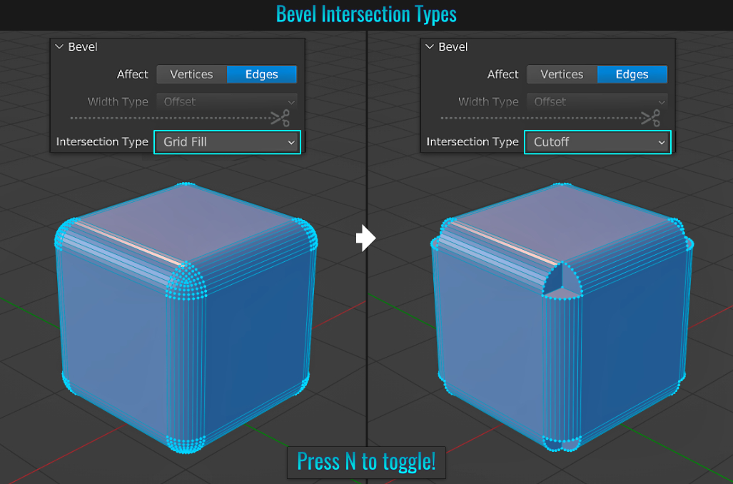
- Multiple Selection Modes Simultaneously
Did you know you could be in more than one selection mode (vertex, edge or face) at the same time? Simply hold down Shift and click on the modes you want! This results in faster mesh editing as you don't need to manually jump around into any specific mode!
- Copy Modifiers
Blender makes it possible to copy individual or all modifiers from one mesh to another!
Copying A Single Modifier
First select the target mesh (the one you want to copy a modifier to), then Shift select the source mesh (the one with the applied modifier in question). Go to the Modifier Properties tab and from within the modifier you wish to copy, click on the small down arrow button and choose Copy to Selected. The target mesh will now have this modifier applied to it (in this case, the SimpleDeform modifier)!
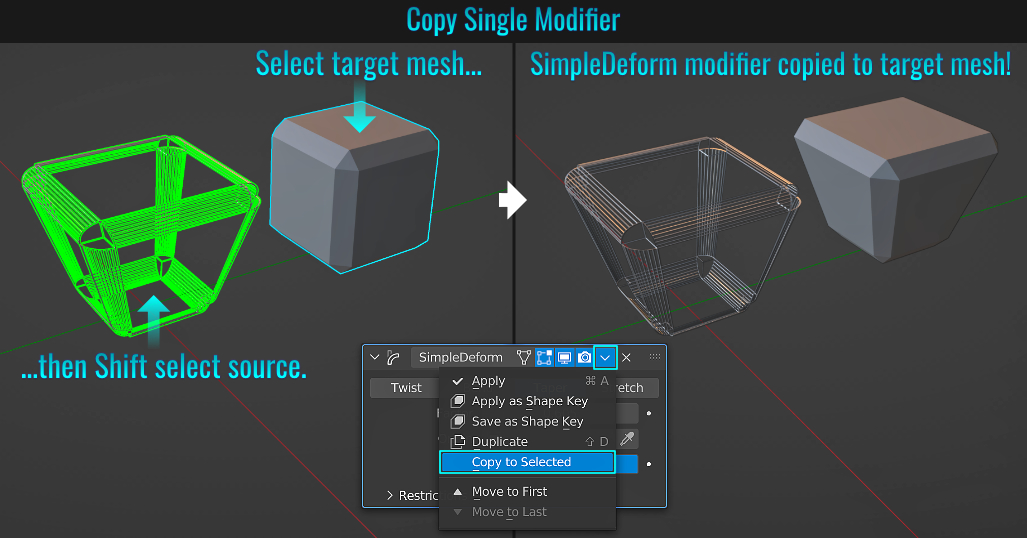
Copying All Modifiers
As with copying a single modifier, start by selecting the target mesh and Shift selecting the source one. Then press Ctrl + L to bring up the Link / Transfer Data popup and choose Copy Modifiers. All modifiers from the source mesh are applied to the target one!
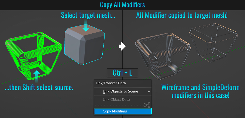
- Display Origin On All Meshes
Normally you would have the mesh origin visible only on the currently selected mesh. But it's very easy to display them on all meshes in the scene! Simply go to the Show Overlays dropdown menu along the top of the 3d viewport and enable both Origin and Origin All (Origin needs to be enabled for Origin All to work!)
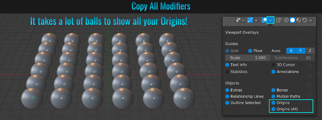
- Quickly Adjust Light Power & Radius
With a light selected, instead of heading over to the light Object Data Properties tab to adjust its power or radius, simply right-click in the 3d viewport instead! The two top options listed from the Object Context Menu are Adjust Light Power and Adjust Light Radius (the second option will be Adjust Sunlight Angle in the even a Sun light is selected). Once you select one of these options, simply drag your mouse left or right to increase or decrease the power/radius respectively (left click to finalize the operation)!
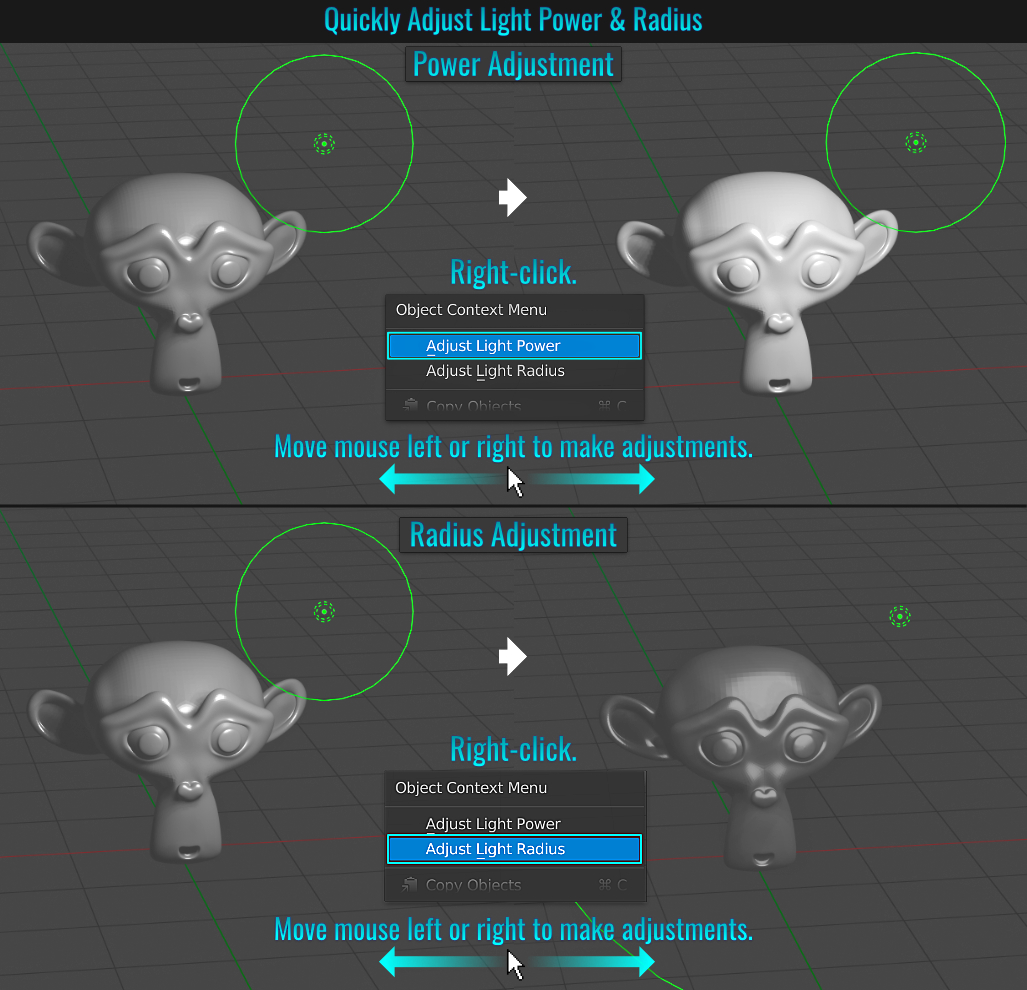
With the mouse cursor placed at a top viewport corner that is adjacent to another viewport (the cursor itself turns into a small cross), simply hold down Ctrl, left-click and drag into the other viewport right next to it. The cursor will change to two small diagonal boxes with a swap arrow in-between them! Left click and voila! Both viewports have now swapped positions!
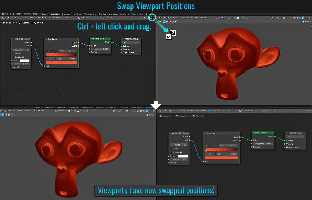
- Hiding, Un-hiding And Isolating Meshes / Selections
Blender offers a lot of control over hiding, unhiding and isolating meshes or sub-selections. Regardless to whether you are in Object or Edit Mode with a selection:
- Pressing H hides it.
- Pressing Alt + H unhides it.
- Pressing Shift + H isolates it (hides everything not selected).
Other things to note:
- While modifying isolated parts of geometry, things like subdivision, loop cuts, etc.. will not affect hidden faces! So it is important to be mindful about this!
- Pressing Tab to go back into Object Mode with hidden / isolated faces will display the full mesh! You'll quickly be reminded when you go back into Edit Mode that there is hidden elements!
- Don't forget that you can use Local Mode (by pressing / or Numpad /). This is only useful in isolating an entire mesh (even with a sub-selection).
- Switching Meshes In Edit Mode
There are a few quick and easy ways to switch from one mesh to another while in Edit Mode and retaining the Select Mode (i.e. vertex, edge or faces). Let's examine how to do this with ease!
From The Outliner
Simply click on the small dot icon next to the mesh's name in the Outliner. That mesh will now be selected while remaining in Edit Mode! Ctrl + clicking on a mesh name's dot adds a mesh to the selection!
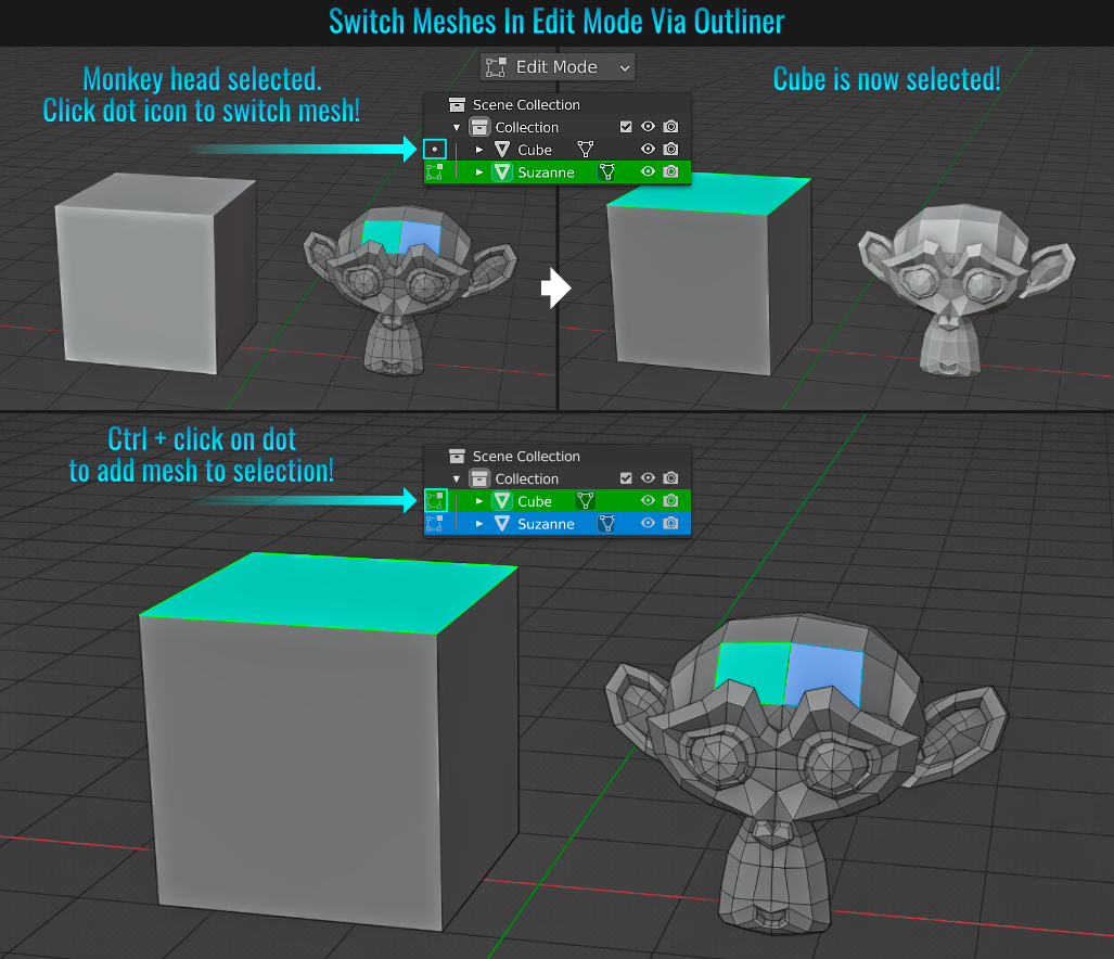
From The Viewport
Alternatively, while you have a mesh in Edit Mode, simply mouse hover over another mesh and press Alt + Q! That hovered mesh will now be selected and maintain the select mode in the process! This even supports having multiple selection modes enabled at once!
(see tip# 159: Multiple Selection Modes Simultaneously)
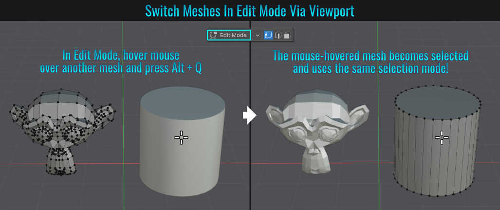
- Correct Face Attributes
Normally, when you modify geometry (say move some vertices or faces), its UVs get distorted. Luckily, there is an easy way to prevent this! You can enable Correct Face Attributes by going to the Active Tool and Workspace Settings Tab > Options panel or the Options dropdown found at the top of the viewport (next to the Auto Mirror and Auto Merge Vertices buttons).
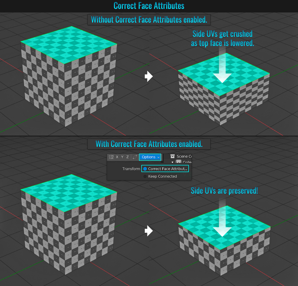
You can change the world viewport background colour by first going to the Viewport Shading menu, changing the Display to Solid, then changing the Background section to World. Finally, from within the World Properties tab, change the Viewport Display panel's Color value to see the effect in the viewport!
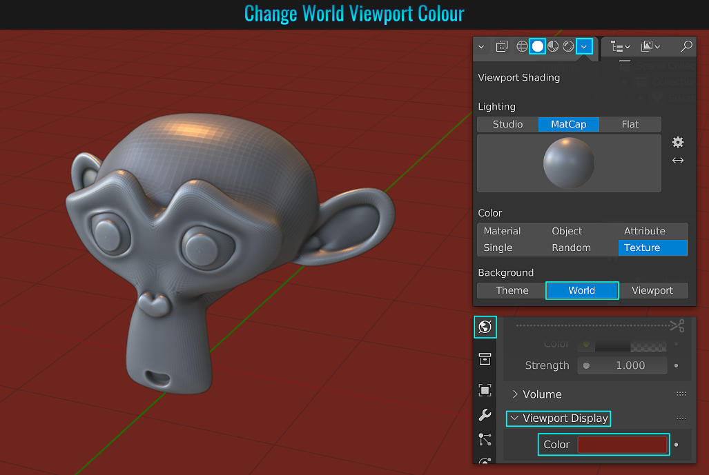
You can also change the viewport background by simply choosing Viewport from within the Background section and changing the colour value from there!
- Change Icon Colours
Did you know you can change the tab icon colours? Go to Preferences > Themes > User Interface > Icon Colors. Here, you will see a series of colour fields, each representing an individual (or portion) of the tab icons! Feel free to experiment and release your inner UI customization desires!
- Change Shadow Colour
You can easily change the colour of a mesh's cast shadow! First select the mesh in question and apply a material (via the Material Properties tab by pressing the New button). Then head on over to the Shader Editor. Add the nodes and connect them as illustrated in the screenshot below. The important thing to note here is that the colour of the shadow is driven by the Transparent BSDF node's colour value!
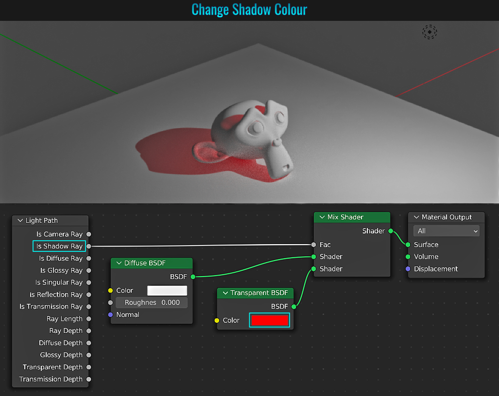
Meshes and their bounds (think bounding box) can be customized. Simply select the mesh and from within the Object Properties tab, open the Viewport Display panel. Here, you'll see options for how the mesh is displayed from within the
Display As drop down menu. These options include: Bounds, Wired, Solid and Textured.
Just below this is the Bounds option (which needs to be enabled via the radial button) that controls the visual
representation of the mesh's bounding box. The Display Bounds Type here include: Box, Sphere, Cylinder, Cone and Capsule.
Changing the mesh display can come in handy if your scene is filled with many high
poly objects that would otherwise be a viewport burden from a performance perspective!
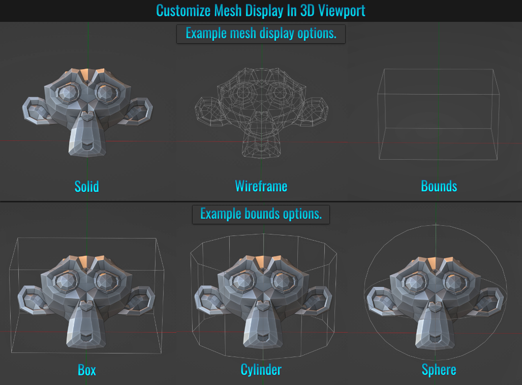
- 3D Cursor
The 3d cursor is a point in 3d space that can be used as temporary reference/offset in which Blender tools can make use of it! When adding a primitive mesh to the scene for example, it makes use of the 3d cursor's location as its point of origin!
The 2d cursor (the 3d cursor equivalent from within the UV Editor) can be used as an offset of sorts when say scaling a mesh's UVs (see tip UV Editor 2D Cursor).
Displaying The 3D Cursor
Simply go the the Overlays menu at the top of the 3d viewport and enable the 3D Cursor radial button! You could add this to your Quick Favorites (see tip Quick Favorites) for convenience!
Moving The 3D Cursor
You can easily place the 3d cursor anywhere in the viewport by holding Shift and right-clicking (or right-click dragging)!
Additionally, there are presets available via the Snap menu by pressing Shift + S! This pie menu has several options
like Cursor to Grid, Cursor to World Origin and Cursor to Selection to name a few! These options really allow you to quickly and easily make the most out of the 3d cursor's placement!
Using The 3D Cursor As
Reference/Offset
The beauty of the 3d cursor is that you can use it as a reference point for transformations for example! You can enable the snap tool (say setting it to vertex snap) and snapping the 3d cursor to any of your mesh's vertices! In turn, pressing . (not the Numpad period) brings up the Pivot Point pie menu. Choosing 3D Cursor sets the Transform Pivot Point mode to make use of the 3d cursor. From this point, all transformations will be affected via the 3d cursor!
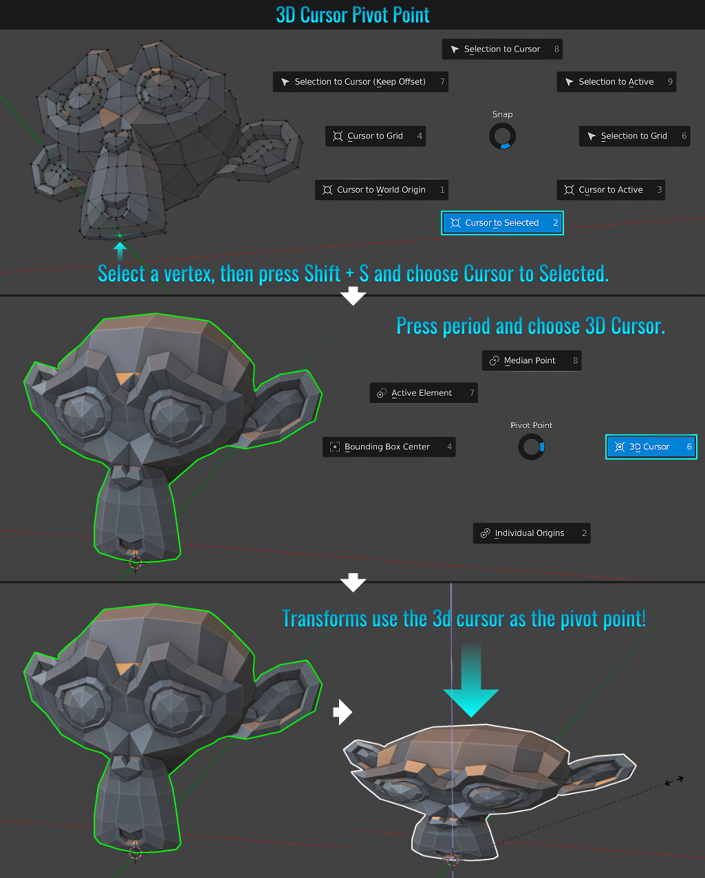
- Select Edges by Sharpness Value
Blender allows us to select edges according to the sharpness angle threshold value! From with the 3d viewport with a mesh selected in Edit Mode and with Edge as the select mode, go to Select > Select Sharp Edges. In the Select Sharp Edges redo panel in the lower left corner of the viewport you can play with this threshold to your liking! This is handy to either mark the selections as sharp edges or as seams for UV editing when dealing with non-organic, hard edged meshes!
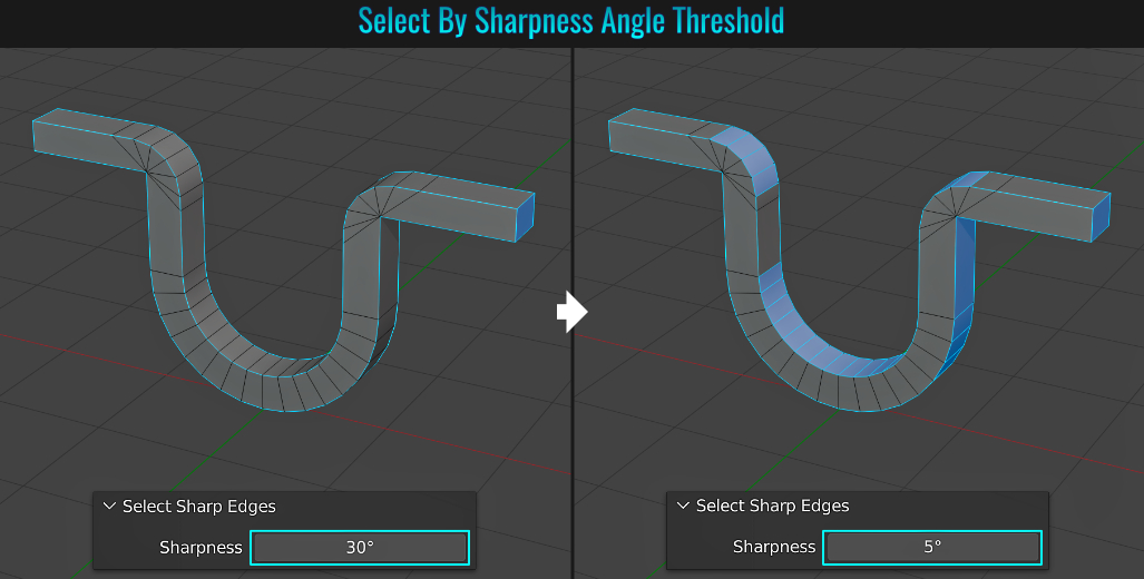
- Fillet / Chamfer Curve Points
Blender cannot bevel points on a curve using the traditional bevel short cut, but there is a way! First ensure that the included Add Curve: Curve Tools add-on is installed (from within the Add-ons side panel selected within Preferences, search for
curve and enable it from the list).
Once enabled, select a point on a curve and press N in the 3d viewport to bring up the right-hand side bar. Within the Edit tab, you'll notice the Curve Edit drop down that hosts a chunk of
curve tools. Clicking the very top option (Fillet/Chamfer) will bring up the Bezier Points Fillet redo panel in the bottom left-hand side of the viewport. Choose between Round and Chamfer to get rounded or sharp bevels respectively while the
Radius simply adjusts the size!
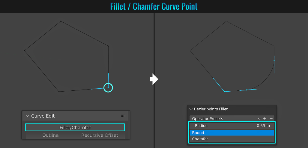
- Copy All To Selected
It's possible to copy values from one mesh to another. Simply choose one of the meshes in your scene and do some sort of rotation for example (it isn't restricted to this of course - there are plenty of other values that can be copied as well), then box select other meshes (or if you manually select others, ensure that the mesh's transform you modified is the active mesh while the others are selected), and from the rotation section within the Object Properties tab, right-click over a rotation value and choose Copy All to Selected! All selected objects should now share the complete rotation values of the original mesh!
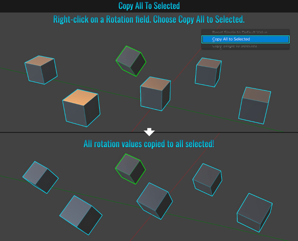
Sometimes you might not want to see overlaid sharp or seam edge markings in the viewport. With a mesh selected and in Edit Mode, simply go to the Viewport Overlays menu along the top of the 3d viewport and from within the Mesh Edit Mode section, simply toggle on/off any of the options (Crease, Sharp, Bevel, Seam)!
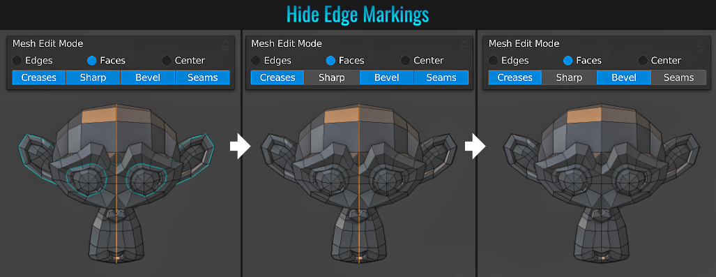
- Material Offset
Modifiers that contain a Material Offset value drives the material index that will affect what the modifier does. For instance, a wireframe modifier's material offset will apply whichever index its value is pointing at onto the wireframe mesh itself!
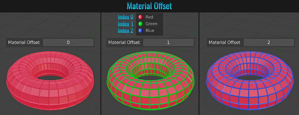
- Panoramic Camera
Creating a 180° panoramic image in Blender is pretty simple! First, from within the Render Properties tab, set the rendering engine to Cycles. Next, add a camera to the scene and with it selected, go to the Object Data Properties tab and switch the
Lens Type to Panoramic and the Panorama Type to Equirectangular! Within the Output Properties, Adjust the Format Resolution / Aspect Ratio to your liking.
Finally, press Numpad 0 to go into the
camera view (the position and framing of the camera is important as this impacts the end result!) and ensure that the viewport's shading mode is set to Rendered! Now your camera will view the scene in all of its panoramic glory!
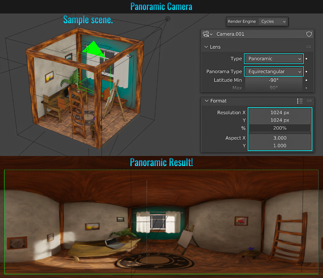
- Free Keyboard Bindings
You can find out which keyboard shortcuts are used/unused. First start by going to Preferences > Add-ons and from within the dropdown menu along the top, choose Development! From the list of add-ons, enable Development: Is Key Free.
To be able
access to this information, you'll need to switch a viewport to the Text Editor. From within this editor, click on the small side arrow along the right hand side of the viewport to bring up the sidebar. Click on the Dev tab and open the Is Free Key
panel. Here you can search for keys in the search field (including enabling specific modifier keys)!
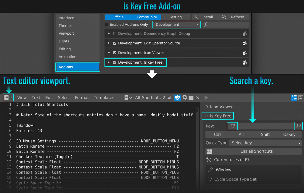
- Relaxing Vertices
There are two types of relaxing; vertices on the actual mesh, or via UVs in the UV editor!
Relaxing Mesh Vertices
Go to Edit > Preferences and from the Add-ons panel, search for mesh and ensure that the Mesh: Edit Mesh Tools add-on is installed!
In Edit Mode with some mesh vertices selected, do one of the following:
- Choose Vertex > Relax from the top 3d viewport menu -or-
- Right-click and choose Relax from the contextual menu.
During the operation, there is a relax redo panel in the lower left side of the viewport where you can adjust the Relax Iteration value to increase or decrease the smoothness accordingly!
Relaxing UV Vertices
From within the UV editor, simply select the Relax tool, use the open/close angle brackets to size it (or press F and drag then click), adjust the strength slider along the top of the UV editor viewport (or press Shift +
F and drag then click) and simply paint on the UVs to relax their vertex positions!
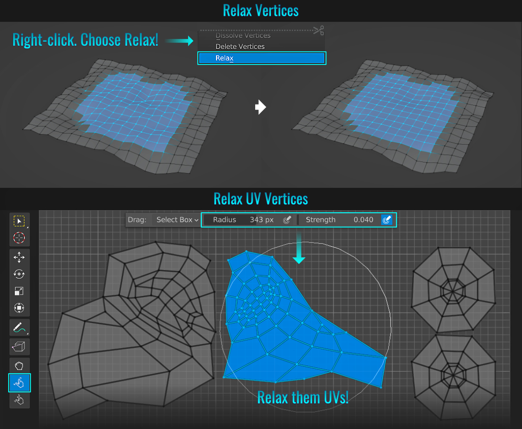
Relaxing Vertices Using A Sculpting Tool
Oddly enough, you can use the sculpting smooth tool to relax vertices on a mesh!
- Select the Sculpting workspace. With the selected mesh in Edit Mode, select the Smooth sculpting brush. Over in the Brush Settings panel (right hand side section of the viewport), open the Advanced sub panel and enable Mesh Boundary from within the Auto-Masking section (this assumes you don't want to mess with border vertices).
- Finally, "paint" over your mesh with the brush (ensure a suitable brush strength and size for efficient smoothing) and watch the vertices within the mesh's boundaries relax!
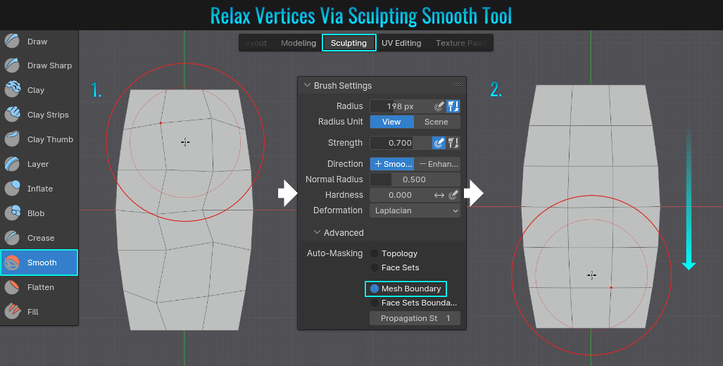
The viewport axis can be found in the upper right-hand corner of the 3d viewport. By default, it is displayed as Interactive Navigation, meaning you can click on the coloured axis circles that represent the axis as a way to quickly reorientate your view
(circles with the axis letters represents the positive directions on the grid while the matching coloured circles without any axis letter represents the negative direction).
But this isn't the only display option! If you go to Preferences and from within the
Viewport section, you can change the way the viewport axis is displayed. Simply change the 3D Viewport Axis dropdown menu to either Simple Axis for a simpler, non-interactive version or Off if you don't care to see it in the first place!
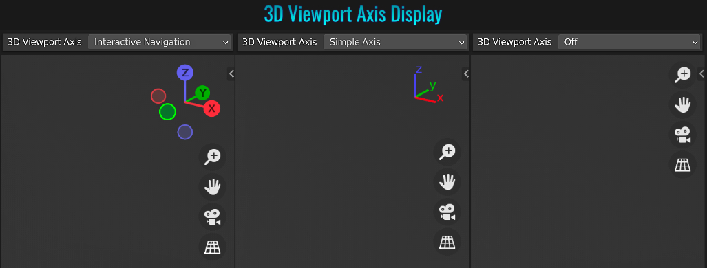
- Lasso Select
Holding down Ctrl while right-click dragging will create a lasso selection! Once the mouse button is released, any mesh(es) with their origin points within the lasso area will result in those meshes being selected! This can come in handy when you need to make a selection among scattered meshes, as this can be quicker than manually adding selected individual meshes one at a time! Holding Ctrl + Shift while right-click dragging will deselect any mesh(es) within the lasso!
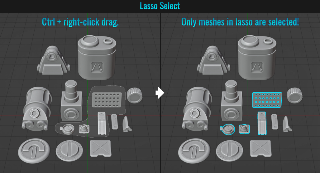
- Extrude Repeat
Blender allows you to make repeated extrusions quite easily using a single operation by selecting whatever you wish to extrude, pressing Alt + E (to bring up the Extrude menu) and choosing Extrude Repeat. In the Extrude Repeat redo panel in the lower left hand side in the 3d viewport, you will need to adjust the X, Y and Z Offsets as well as the Steps value!
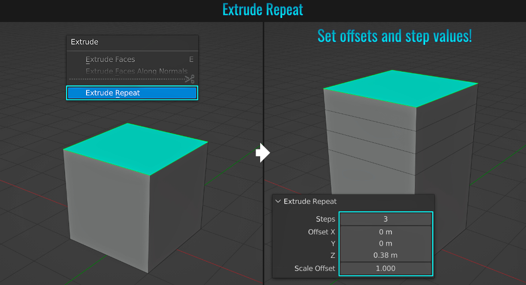
- Edge Bevel Weight
Did you know it is possible to have multiple various bevel widths using a single bevel modifier? Start by applying a bevel modifier to your mesh. Increase the Amount value to the maximum the mesh can hold. Why? Because in the steps that follows, any
bevels you create can only be as large as the amount setting (but can be smaller). By making this value big, you are giving yourself some extra bevel padding space (this will make sense soon enough).
Next, set the modifier's Limit Method dropdown menu to Weight.
At this point, all the bevels on the mesh should disappear! This is because the modifier now requires some edge weights for beveling! Go into Edit Mode and select a set of edges, press Ctrl + E (to bring up the Edge menu) and choose
Edge Bevel Weight and start left-click dragging to set that bevel! Rinse and repeat, selecting another set of edges and doing another edge bevel weight click-drag operation and so on. You can create a wide variety of bevels, all using the single bevel modifier on the mesh!
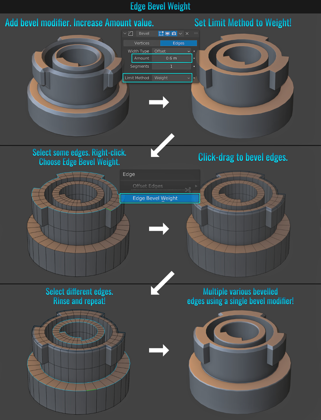
- Stereoscopy
Creating stereoscopic images in Blender is quite simple. Start by creating two cameras that frame the scene differently. Change the names of the cameras so that they have the suffix using _L and _R respectively. In the Output Properties tab, enable Stereoscopy! Select a camera, go into the Object Data Properties tab and play with the Convergence Plane Distance and Interocular Distance values! You should notice that the 3d viewport has shifted red and green channels!
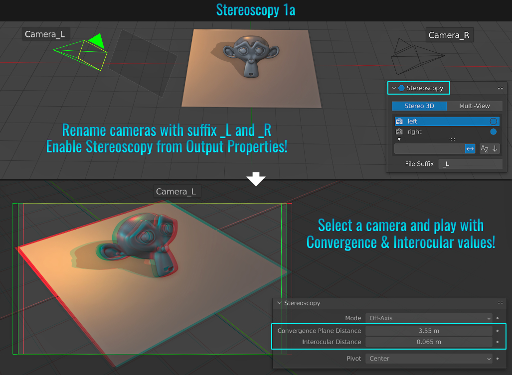
To view both cameras simultaneously, head back over to the Output Properties tab and from within the Stereoscopy section, switch from the default Stereo 3D mode to Multi-View!
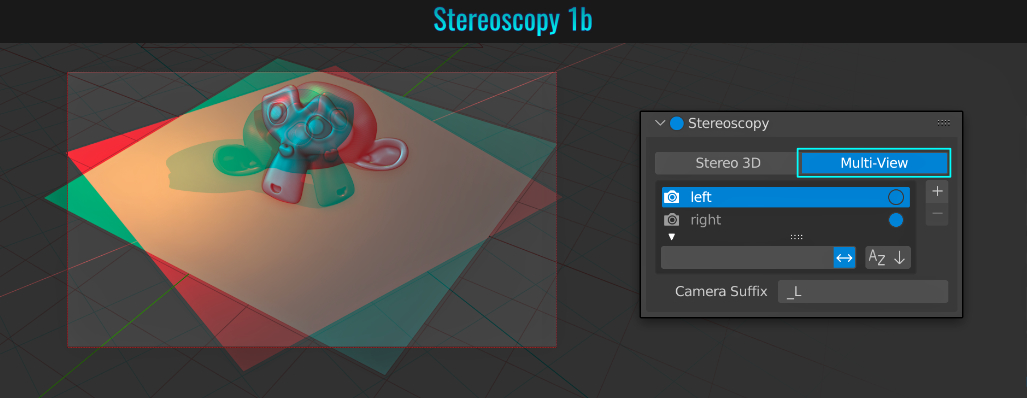
You can check out the stereoscopy online documentation for more information!
- Pivot Location Only
It is possible to use rotations to only affect the location of a mesh. With a mesh selected, press . (not on the numpad) to bring up the Pivot Point pie menu. Here, you'll notice an option called Only Locations (it contains a checkbox
as this is a toggle feature).
By selecting this, any rotation to the mesh will not affect its rotation but rather its position! So if you then choose 3D Cursor after toggling on Only Locations for example and start rotating the mesh, its position will
rotate using the location of the 3d cursor as its center point! Selecting two or more meshes and setting the pivot point to something like Bounding Box or Median Point will result in those meshes positions rotating around the selections central point!
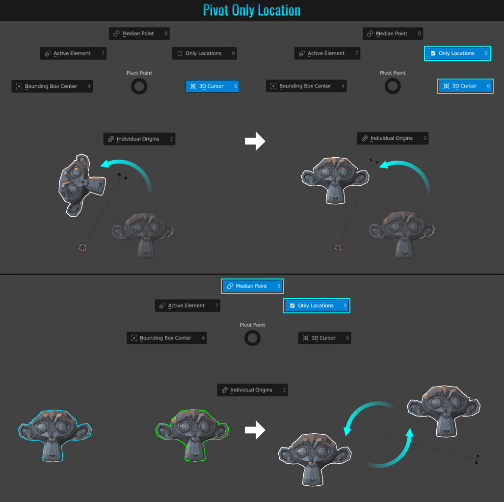
- Collection Visibility Toggle
When dealing with collections, it is possible to quickly hide/unhide them by noting a specific order of a collection within the outliner and pressing Shift + that collection number! So for the example, if you wanted to hide the entire second collection in the list, simply press Shift + 2! The same shortcut toggles that collection's visibility!
- Principled Volume
The Principled Volume node can add a volumetric effect in combination with scene lights! Start by going into the Shading workspace and switching the Type of data to take shader from: (the small dropdown menu in the upper left hand corner) from Object
to World. Then press Shift + A and choose Shader > Principled Volume.
This will add that node into the shader editor. Simply plug this into the Volume input of the World Output node. Adding light(s) creates a
volumetric fog effect! Each light has a Volume slider that can increase or decrease its own fog-like effect! You can further tweak the volumetric effect by going into the Render Properties tab and adjusting values from within the Volumetrics panel!
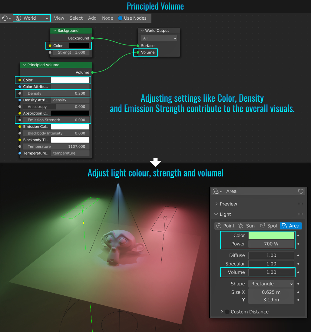
- Lofting Shapes/Geometry
It's possible to loft shapes in Blender. Simply create some shapes, attach them into a single mesh and with all vertices or edges selected, simply press Ctrl + E (to bring up the Edge contextual menu) and choose Bridge Edge Loops. From the lower left-hand redo panel, there are plenty of options at your disposal in controlling how the loft is affected! It is important to note here that if the total number of vertices in each shape varies from one another, the lofted end result will not look good. It is highly recommended to ensure that each shape's total vertex count is identical to each other for best results!
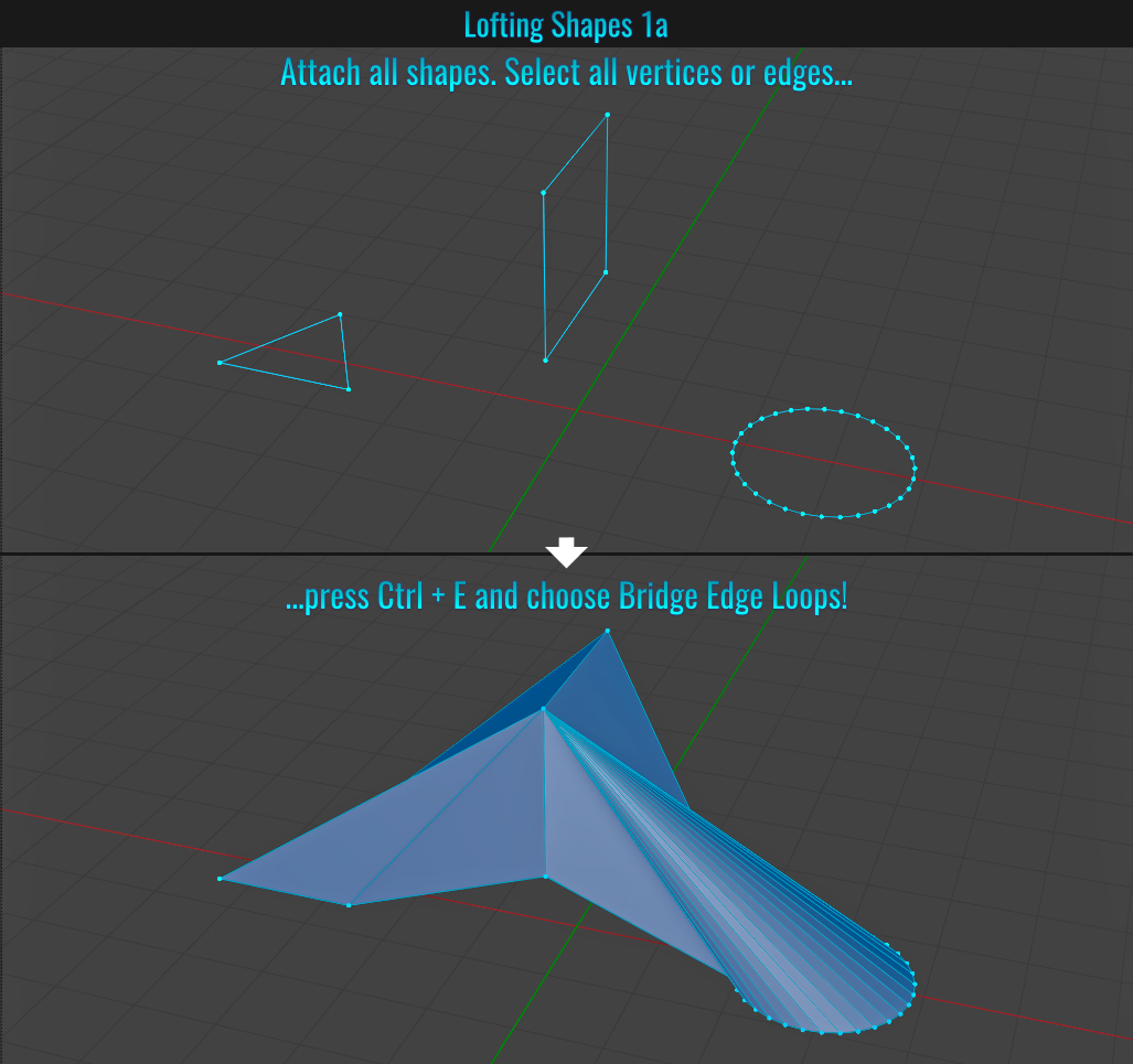
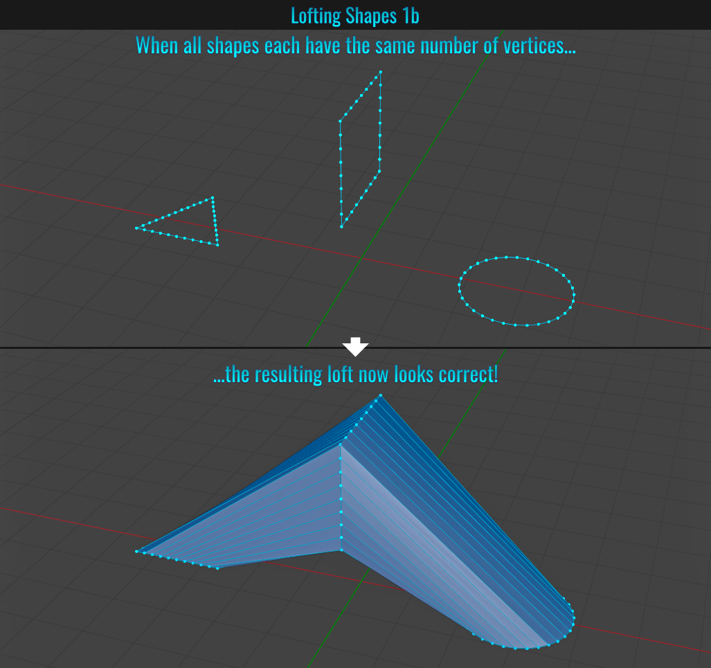
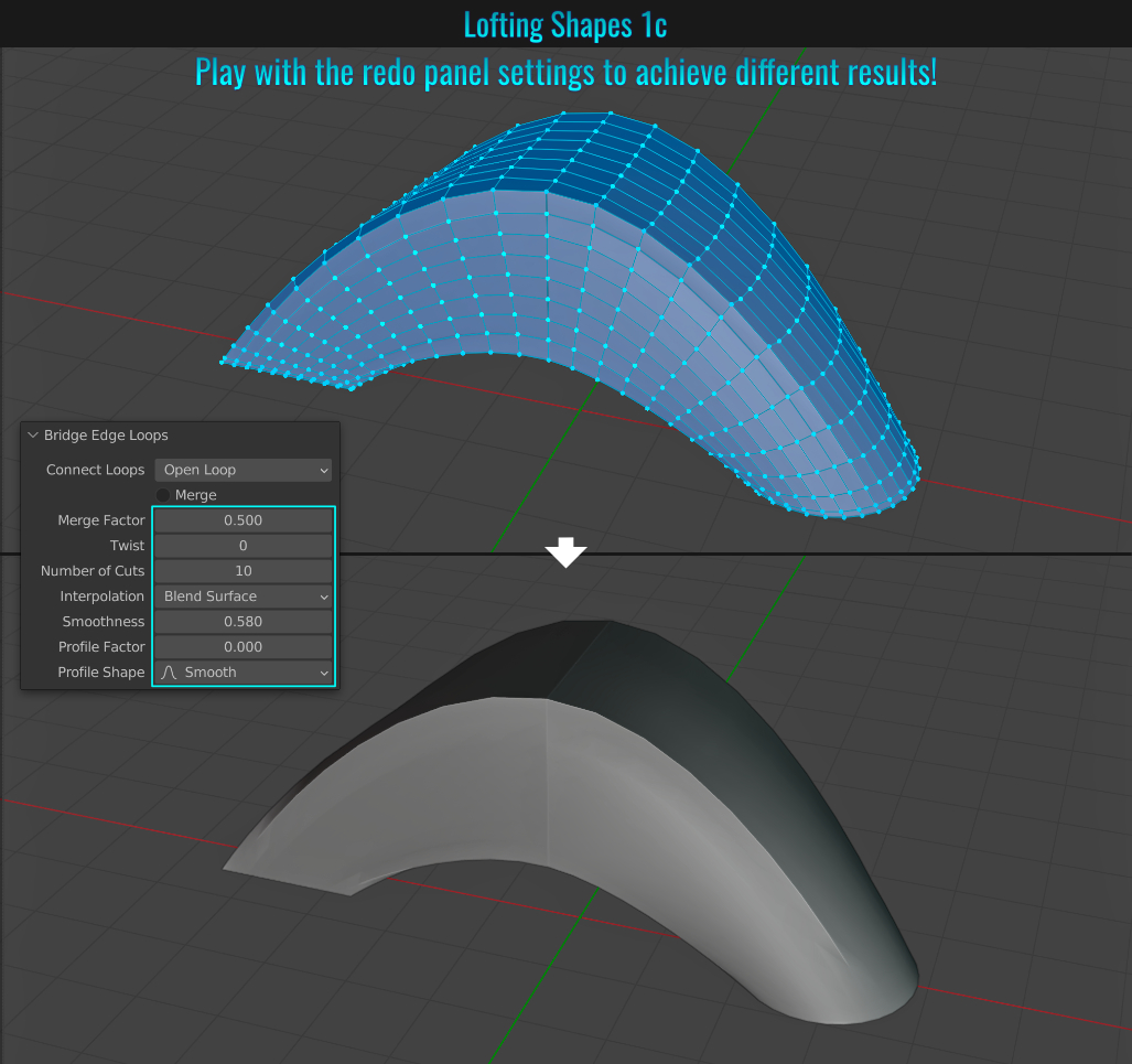
You're not limited to lofting shapes however. It is even possible to "loft" the end pieces of a non-manifold mesh as well!
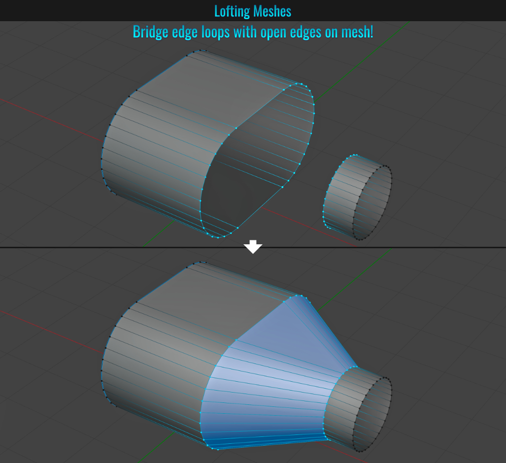
- Flipping Image
Did you know you can flip an image in the Image Editor? Simply go to Image > Flip and choose either Horizontal or Vertical! Of course, you're not limited to flipping, as this menu also allows for things like Invert, Resize, Reload and even Replace among other options!
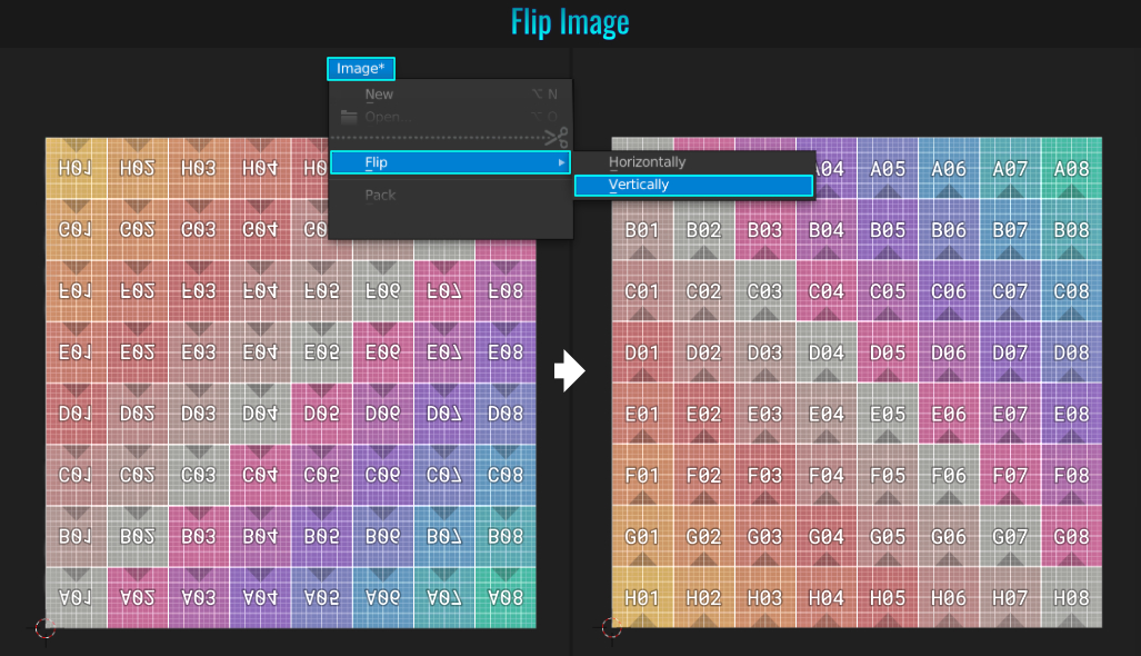
- Follow Active Quad
When dealing with curved mesh (like say a pillar arch for instance), it is possible to quickly generate straightened UVs! A checkerboard pattern was used in the Base Color slot of the material to see how things look initially and afterwards.
Start by selecting all the faces on the arch
(or other curved meshes) and Shift + click on a specific face (ideally as square as possible) to create an active selection. From within the 3d viewport, press U and choose Reset from the UV Mapping dropdown menu. Not doing this can have
unwanted results later on! Next, Press U once again and this time choose Follow Active Quad, and in the resulting popup, simply click Ok! Notice that within the UV Editor, the arch's UV island is now straightened out!
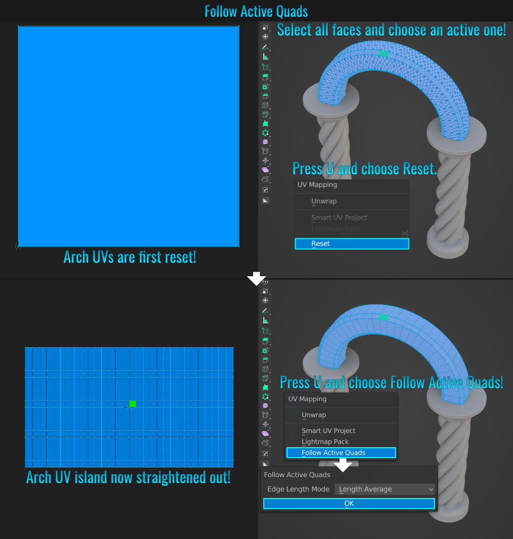
- Pack Resources
By default, any external files like textures for instance is not included when saving your scene! But there is a way to ensure that textures do come along for the ride! Simply go to File > External Data > Pack Resources. Now when you save the scene, any eligible
external files (like textures) will be included in the blend file! It's important to note that not all external files can be packed in (such as movie clips).
If you want to ensure that all current and future eligible external files get included, choose File > External Data >
Automatically Pack Resources instead! Either way, you'll know when something is packed by noticing the packed icon next to the file path name!
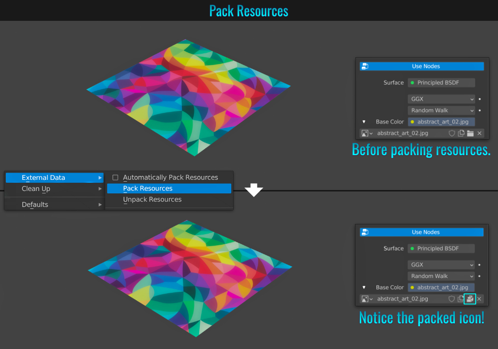
It's quite easy to display the direction of normals in Blender. First start by going into Edit Mode. Then, from within the Show Overlays dropdown menu, navigate to the bottom. Here, you'll find the Normals section. There are three togglable buttons, each for displaying vertex normals, split normals and normals respectively! It's possible to toggle the visibility two or all three at the same time!
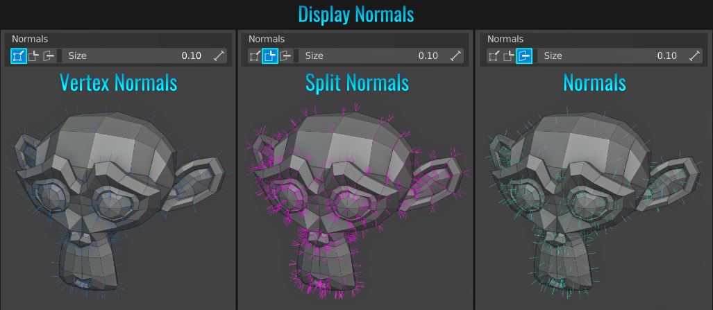
- Copy Attributes
Blender offers an included add-on that allows to copy attributes from one mesh to another! Start by going to Edit > Preferences and from within the Add-ons panel, search for "copy" and enable Interface: Copy Attributes. From a scene with two (or more) meshes, first select the mesh(es) that you wish to have an attribute copied to, then finally Shift click the mesh that you wish to copy attributes from (this mesh becomes the active one while the other mesh(es) are selected). Then simply press Ctrl + C and choose the attribute you wish to see copied via the Copy Attributes menu! Any attribute chosen will be reflected in the selected mesh(es)!
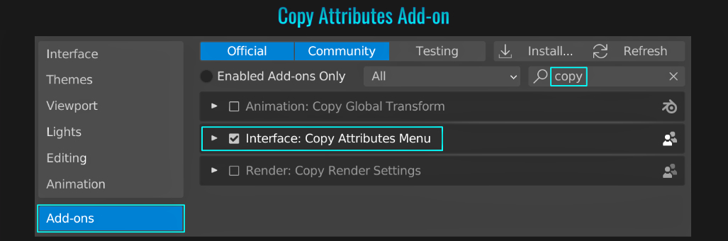
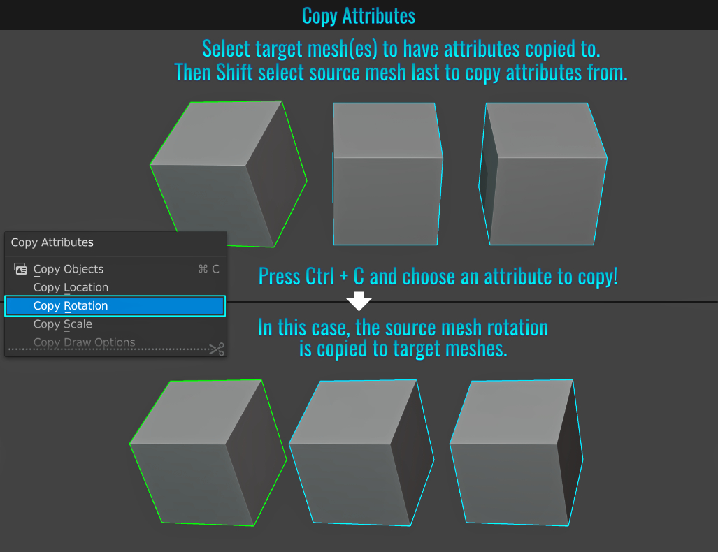
- Collection Instance
When you press Shift + D to duplicate a mesh, the overall scene triangle count increases, while instancing meshes (Alt + D) does not! It is possible to put mesh(es) into a collection and use that as an instance (which can be reused without adding
more triangle bloat!)
With the desired mesh(es) selected, press M to bring up the Move To Collection popup, choose New Collection and create a new collection. Press Shift + A, navigate to Collection Instance and from
the dropdown menu, choose the collection you just created. Notice in the Outliner that there is a newly instanced collection! With this new instanced collection selected, simply duplicate it. There will be no added traingles to the scene!

- Constraint Moving/Scaling Using Middle Mouse Button
After pressing G or S to move/scale a selected object, you don't have to constrain to an axis by then pressing the relevant axis button! Alternatively, you can press and hold the middle mouse button and depending on which direction you drag the mouse will determine which access the movement will be constrained to! Releasing the middle mouse button once the constraint is established continues to lock the object's movement/scale along that axis!
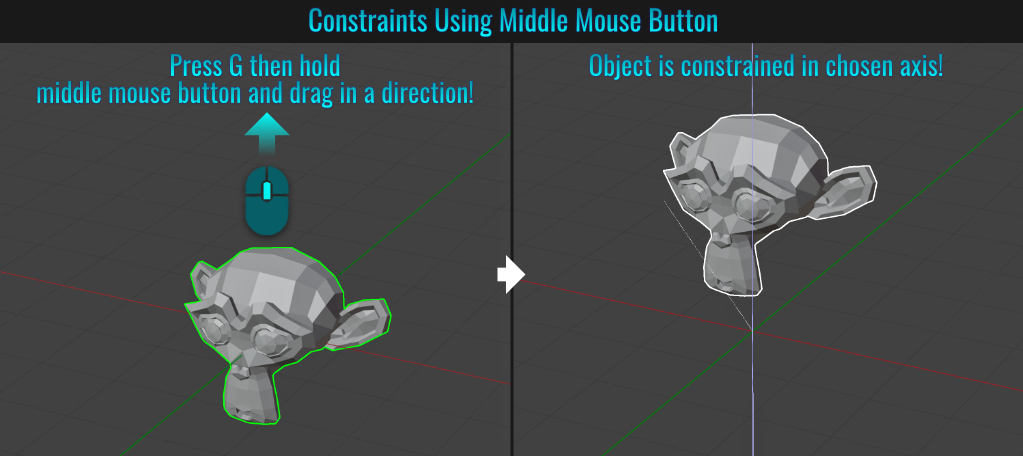
- Make A Quad Sphere
Sometimes it might be desireable to start with a quad-based sphere (no single vertex poles that can cause surface deformations when subdividing, or starting with a quad sphere to start sclupting keeping with only quads for example). There are basically two solutions to this.
Method 1: Manually Create From A Cube
- Start by pressing Ctrl + A (to bring up the Add menu) and choose Cube.
- Then either add a Subdivision modifier or press Ctrl + (1 - 5) as its shortcut! Notice that it isn't perfectly round!
- Finally, Add a Cast modifier and set the Factor value to 1! Easy as that!
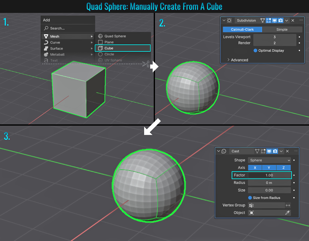
Method 2: 3D View: MACHIN3tools
If you don't have this free Blender add-on installed already, grab it from Gumroad and once
installed and enable, in the 3d viewport simply press Ctrl + A and choose Quad Sphere. Even easier than the first option!
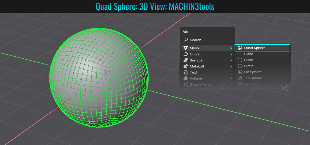
Method 3: Add Mesh: Extra Objects
The method for doing this from the Add menu is to first ensure that the Add Mesh: Extra Objects add-on is installed (comes with Blender) and then you have the option to add a rounded cube. Once this primitive is added, simply open up the Add Round
Cube panel in the lower left hand side in the viewport and change the Radius value from its default setting of 0.20 to 1. The rounded cube is now a quad sphere! Altering the Arc value will change the "quad sphere's" segments!
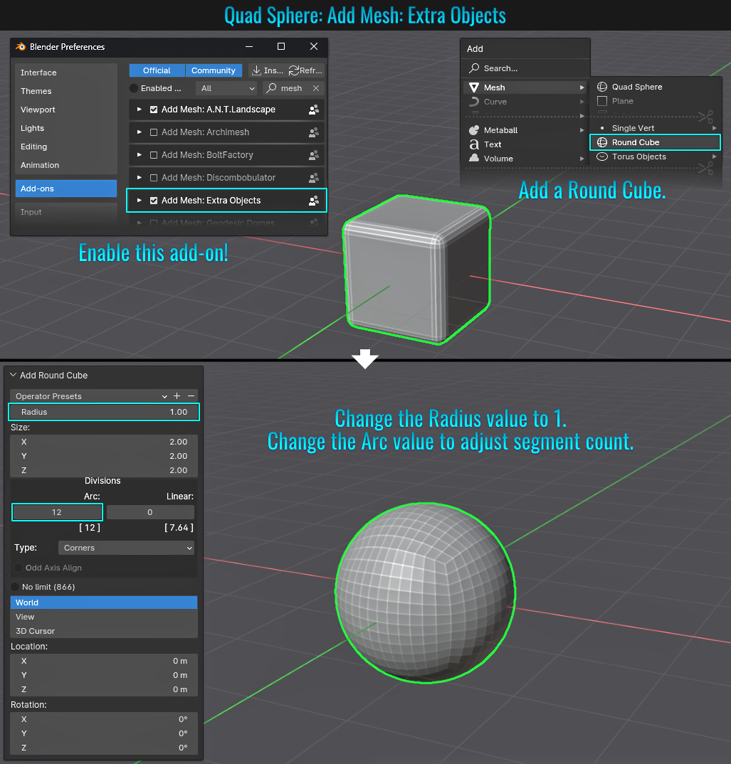
- Bridge Faces To Create Tunnel In Mesh
The Bridge Face tool is quite versatile, allowing you to connect two separate faces on the same mesh. Plenty of features are availble from adding many cuts and twisting the connection, changing its interprolation, smoothness and profile shape among others!
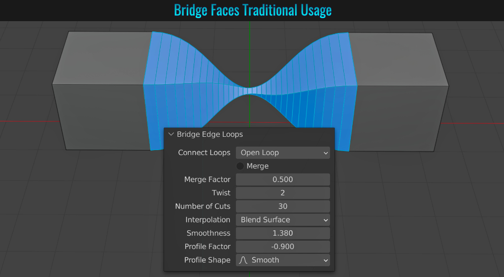
But there is another common use for the Bridge Face tool, and that is to create a tunnel in the mesh! Start by selecting two faces on a mesh (normally opposite of each other) and then right-click and choose Bridge Faces. You'll be left with a tunnel through the mesh, bridging where the two selected faces use to be!
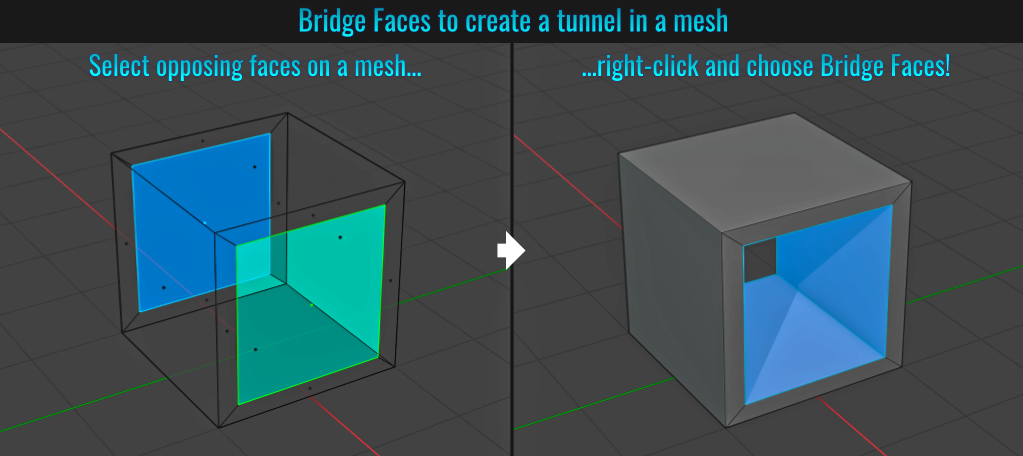
- Applying Modifiers
There are a few ways to apply modifiers, ranging from manually applying a single one to applying all at once. Let's examine how these can be acheived.
Applying All Modifiers
A quick and easy way to acheive this without using any add-ons is to simply select a mesh with some modifiers on it, right-click and choose Convert To > Mesh (despite it already being a mesh)! All modifiers are instantly applied! Alternatively, with the
selected mesh(es) in question, you can also press Ctrl + A (to bring up the Add menu) and choose Visual Geometery To Mesh which basically does the same thing as converting to mesh! It is important to note that this last method only works if you
don't have the Interface: 3d Viewport Pie Menus add-on installed!
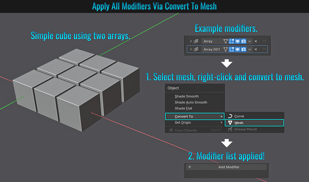
Another way is to install the included Modifier Tools add-on (which provides extra functionality above the modifiers list - like providing an Apply All button among other options).
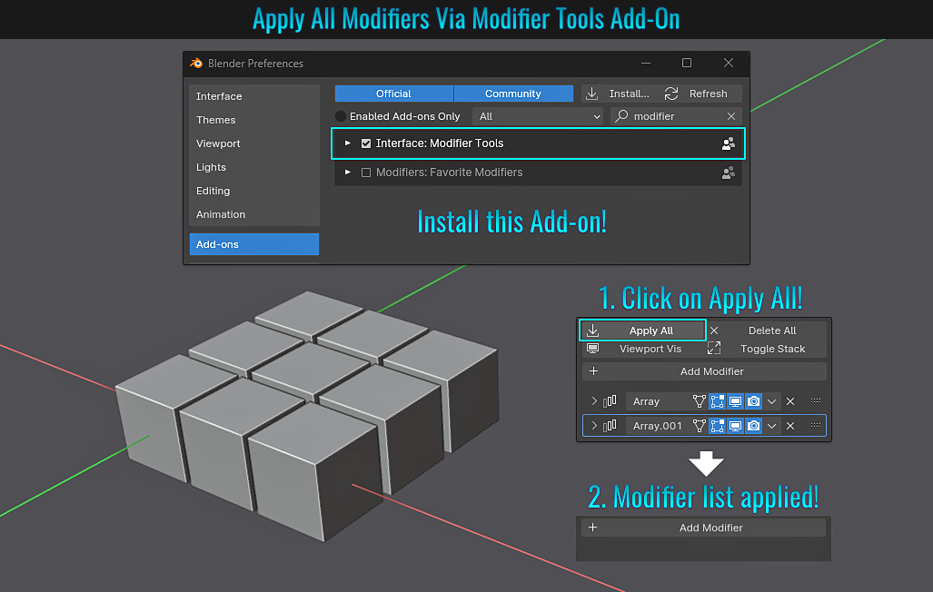
Applying Individual Modifiers
To apply an individual modifier, first click on the down arrow button next to the modifier's name and choose Apply (or simply hover the mouse cursor over the modifier in question and press Ctrl + A).
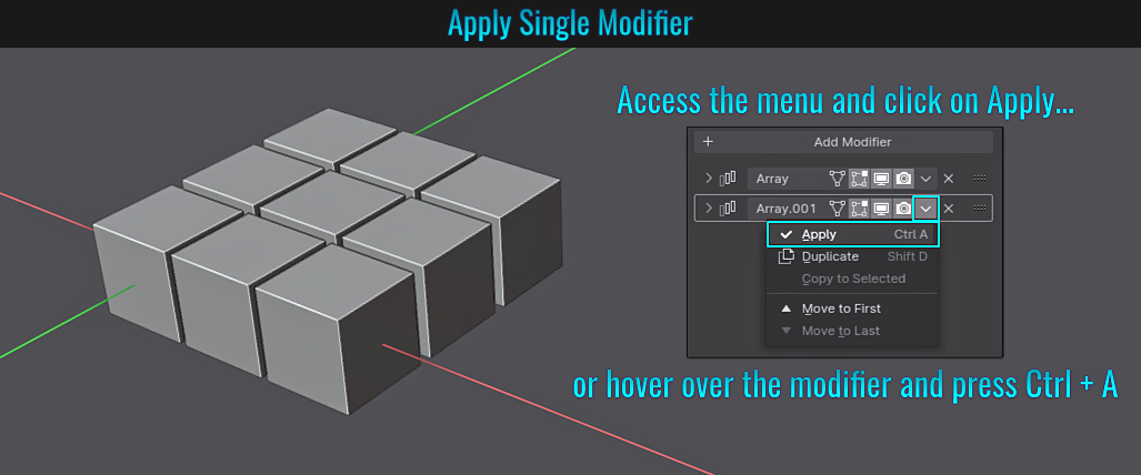
Disabled/Greyed Out Apply Button
From time to time, you may notice that when you try to apply a modifier, the Apply option is disabled/greyed out! Don't panic! The following will list two possible reasons for this (one being outdated) and the accompanying solutions as well!
- Reason #1: You are in Edit mode (this is likely the only current reason which still applies regardless of which Blender version you are using).
Solution: Simply be in Object mode, as you cannot apply modifiers while in Edit mode!
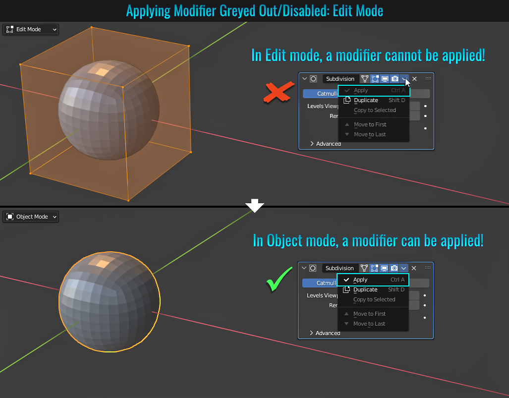
- Reason #2: Apparently when using Blender 3.1 or lower and you have an instanced mesh (thus sharing the same data), a modifier cannot be applied (even in Object mode).
Solution: In Object mode and with the mesh you wish to apply the modifier selected, go into the Object Data Properties tab and click on the user display number button next to the shield icon. This in essence makes that mesh into a single user copy, which means it is no longer using a shared datablock! The good news here is that Blender 3.2+ will allow you to apply a modifier on a shared user mesh without the need to do any of this!
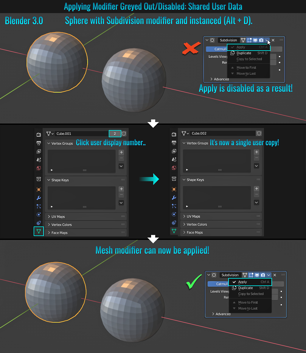
- Adding Save Versions
When saving a file, type in the file name then click out of the file name text field. The text .blend should be automatically appended to the file name. Now press numpad + or - which will add or subtract a numerical value respectively in the file name (right before the .blend part)! Holding Shift + numpad + or - increases / decreases by 10 while holding Ctrl + numpad + or - increases / decreases by 100!
- Twisting Curves
It's possible to twist curves! To do this, simply select a point on a curve (in this example, a simple path curve has a curve containing three circles applied as a bevel) and with proportional editing enabled, press Ctrl + T then left-click drag the mouse to add the amount of desired twist to it! The result gives a twisted bunch of cables!
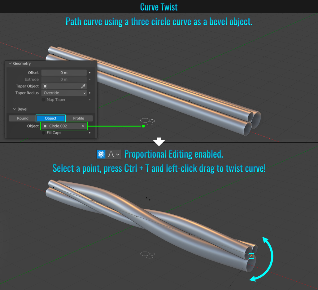
- Bridge Edge Loop For Arches
Closed Arch From a Box
To create a arch from an box, you could select some opposite edges and bevel them with a clamp and enough segements (see tip Bevel Clamp Overlap), but here's a different way!
Start with a box (in this example, it's rectangular).
In Edge mode, select a set of opposing edges, right-click and choose Bridge Edge Loop. In the redo panel located in the bottom left-hand side of the 3d viewport, set the Number of Cuts to have enough segments for rounder definition, and
finally change the Interpolation value to Blend Surface!
There you have it! An easy arch for say a machine part or the foundation for an archway in architecture!

Open Arch From Pillars Mesh
The exact process above applies to pillars in the creation of an open arch! Just make sure both pillars are attached as the same mesh before hand. The tops of the pillars mesh can be either capped or open, or even one capped and the other open. it doesn't matter. If both are capped, you can select
those capped faces to bridge instead of selecting the edges. In the end, it all just works! The following example shows one top open and the other capped!

- Instancing On Vertices
One neat way of using instancing is to have instances of a mesh placed on another mesh's vertices (it will all make sense)! In the example below, the goal is to add rivets along a fixed distance inside the surface of a panel. So alongside said panel, create a rivet (in this case, a simple
UV Sphere).
- Select the face(s) of the panel in question and duplicate it by pressing Shift + D, then right-click to cancel its transforms. Then press P and choose Selection to make it its own mesh. With this duplicated panel's face(s) selected, go inset to the desired amount by pressing I. Once the inset is established, press Ctrl + I to invert the face selection and press X and choose Delete Faces. We'll call the faces that remain as the insetted panel.
- Next we need to ensure that the origin points of both the rivet (which is assumed to be in its center) and the insetted panel are in the same location. If origins are not visible, go into the Viewport Overlays drop down menu and ensure that the Origins radial check box is checked. With the rivet mesh selected, press Shift + S and choose Cursor to Selected. Next, with the insetted panel selected, go to Object > Set Origin > Origin to 3d Cursor.
- Next, select the rivet, then hold Shift and click on the insetted panel, press Ctrl + P and choose Object (Keep Transform).
- Now for the instancing part! Head over to the Object Properties side panel and from within the Instancing panel, click the Vertices button. Now an instance of each rivet is placed centered along each vertex of the insetted panel! The beauty here is that you can add or remove vertices along the insetted panel's edges and the rivets will add or subtract accordingly! To make each rivet their own mesh, select the insetted panel, press Ctrl + A and choose Make Instances Real!
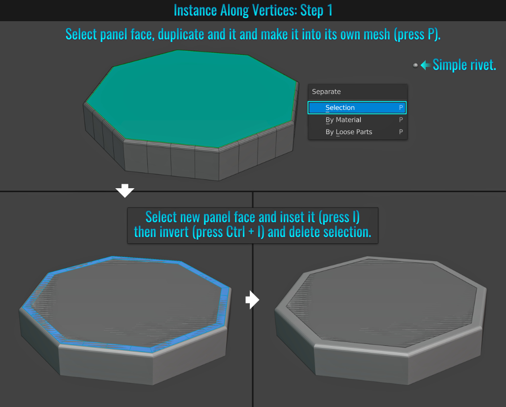
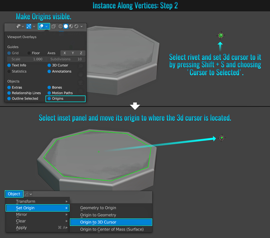
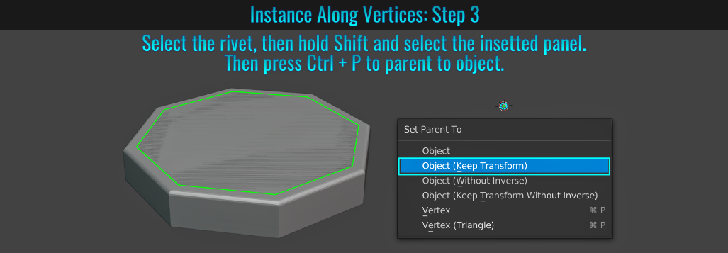
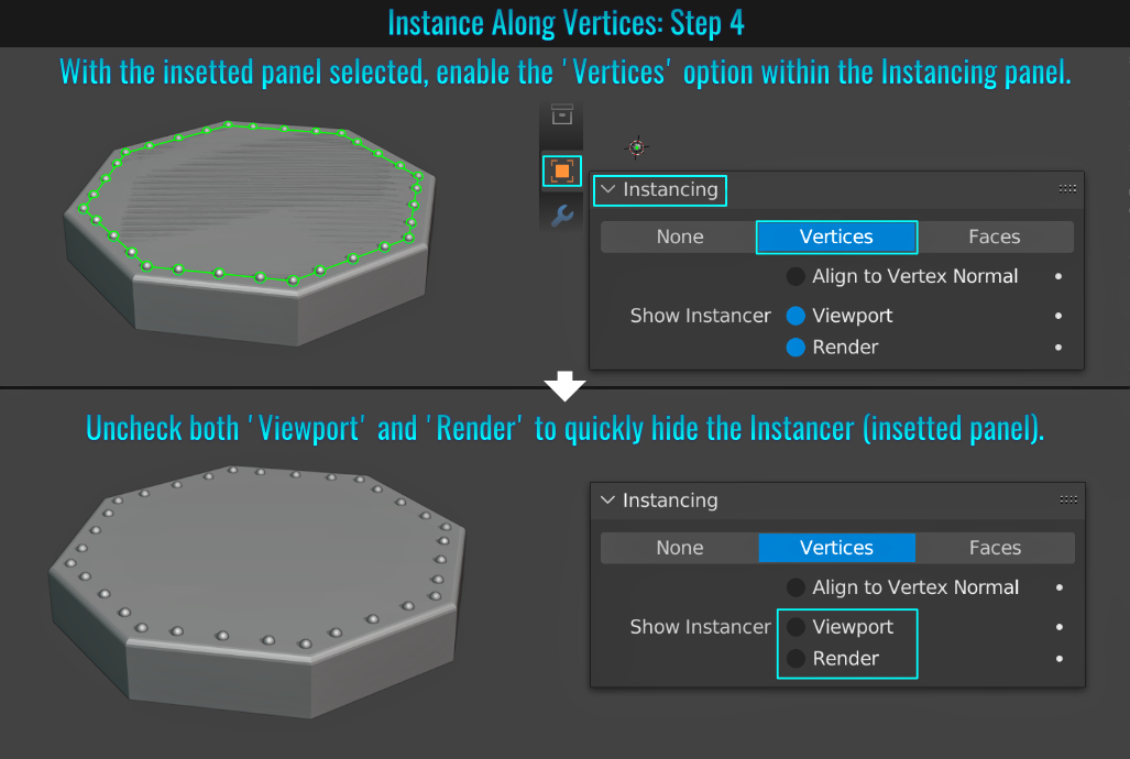
- Volumetric Rays Using Geometry
It's quite easy to create volumetric rays! To begin with, ensure that the rendering engine is set to Cycles. Next, select the glass mesh in the window, duplicate it (Shift + D) and right-click to cancle its transforms. Press P > Selection
to make them their own object. With their faces selected, extrude them (press E) inwards into the room and lower them so that they pass through the floor. This will result in "geometric beams".
Assign a new material to this mesh (go into the Shader Editor and hit the new
button at the top) and delete the Principaled shader node. Press Shift + A to bring up the search feature, look for and choose the Emission node. Finally, plug this node's output into the Volume input of the Material Output
node! You can adjust the Emission node's strength and colours to your liking! There you have it, quick and easy geometry based volumetrics!
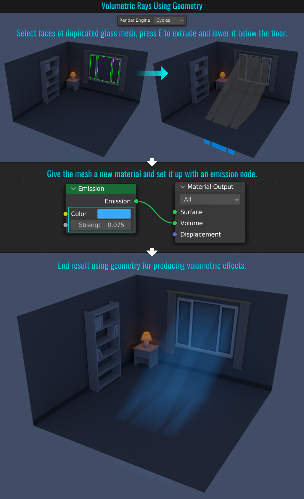
- Auto Mixing Nodes
With the included Node Wrangler add-on (you'll need to enable it from within the Preferences > Add-ons panel), it's possible to select two nodes that you wish to mix together and press Ctrl + 0 (zero). Node Wrangler will know what mixer to use automatically and connect all nodes together!

- Auto Position One Mesh To Another
MACHIN3tools is an useful add-on that is not free, but isn't expensive either (cheapest version costs $1 - please see the useful_blender_setups page and explore the Useful Add-ons section to see more). With this add-on enabled (and the Align option is enabled from withint its preferences), a quick way to move one mesh into the same position as another is to first select the target mesh (the one you want moved) and then press Shift and select the source mesh (the one you want to move the target mesh to) and finally press Alt + A!
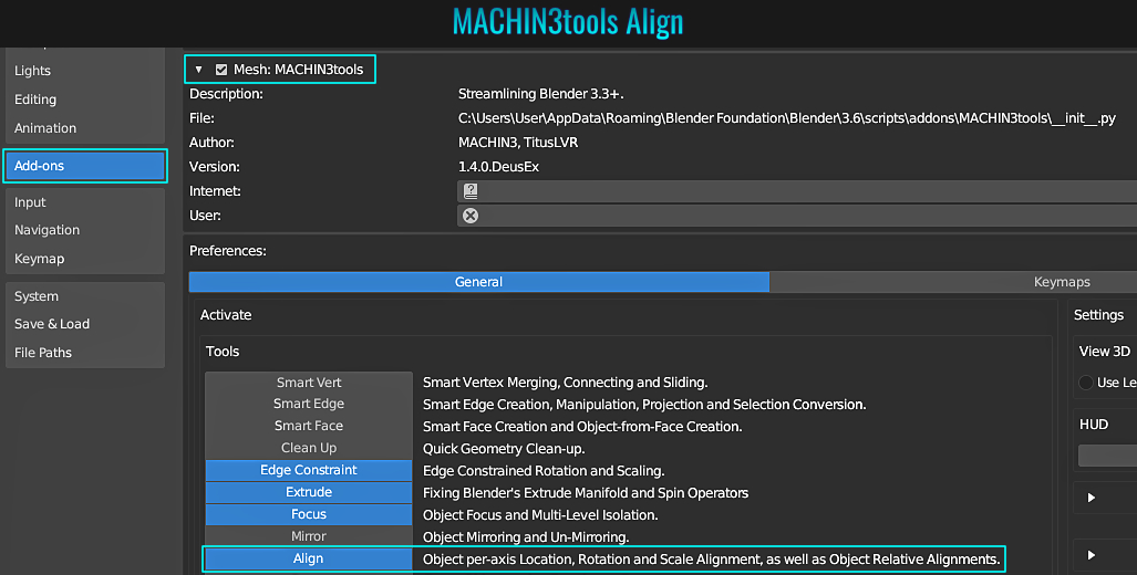
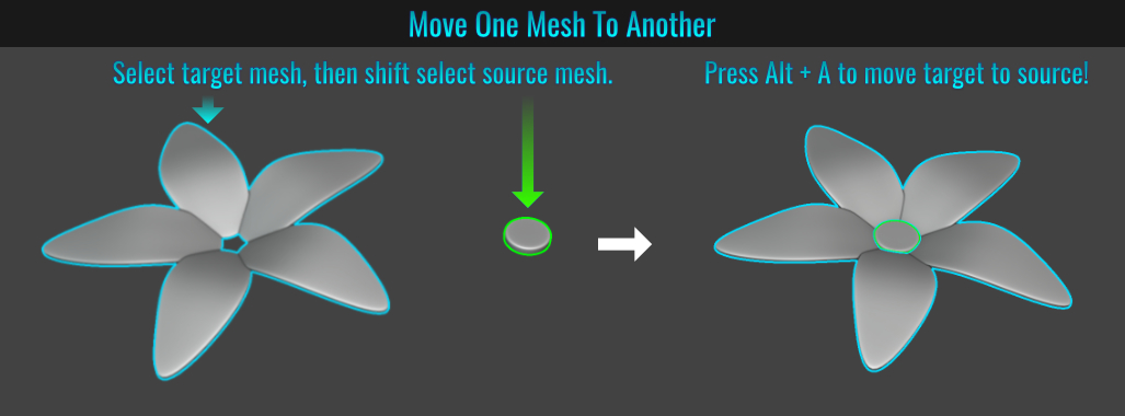
- Dissolve Using Face Split & Tear Boundaries
When it comes to dissolving vertices (Ctrl + X), there are a few options in the lower left hand side redo panel. Here's a quick over view of those options:
Face Split
Dissolving vertices can result in larger, uneven n-gons. The Face Split optiion limits the dissolve to using corners of faces that are connected to vertices.
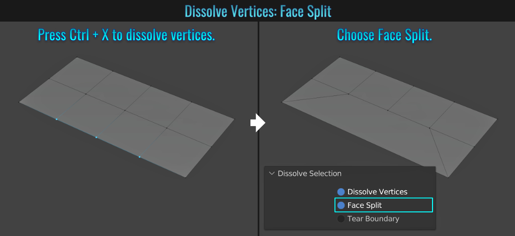
Tear Boundary
This option splits off face corners as opposed to merging faces!
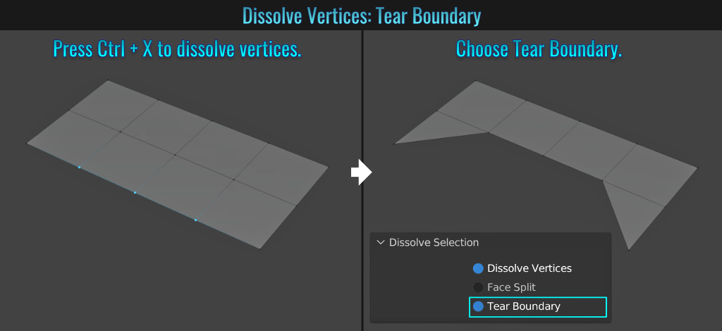
- Adding UV Grid
Whenever you start unwrapping a mesh, it's a good idea to have some sort of checker pattern applied so you can easily spot and correct any UV stretching/warping! An easy way to set this up is to add a material to your mesh, and from within the Shader Editor, press Shift +
A and from within the Texture catergory, select an Image node.
Within this node, simply click on the + New button, set the resolution size and from within the Generated Type dropdown, change the default Blank setting to
either UV Grid or Color Grid (both offer checkerboard patterns!) Now connect this node's Color output to the Base Color input node of the Principaled BSDF (or whatever shader you are using) and you should see the uv grid show up on your mesh in the
3d viewport (make sure the 3d viewport display is set to Material Preview).
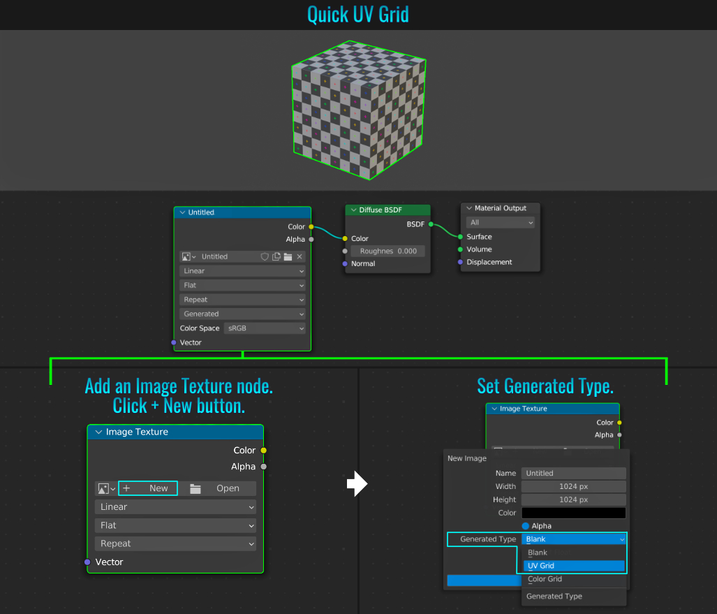
- Expand All Collection Objects
When dealing with a collection, sometimes you may want to expand all objects in it. An easy way to do this is while holding down Shift, click on the arrow in front of a collection. This will result in not only expanding the collection iteself, but all objects contained within it as well!
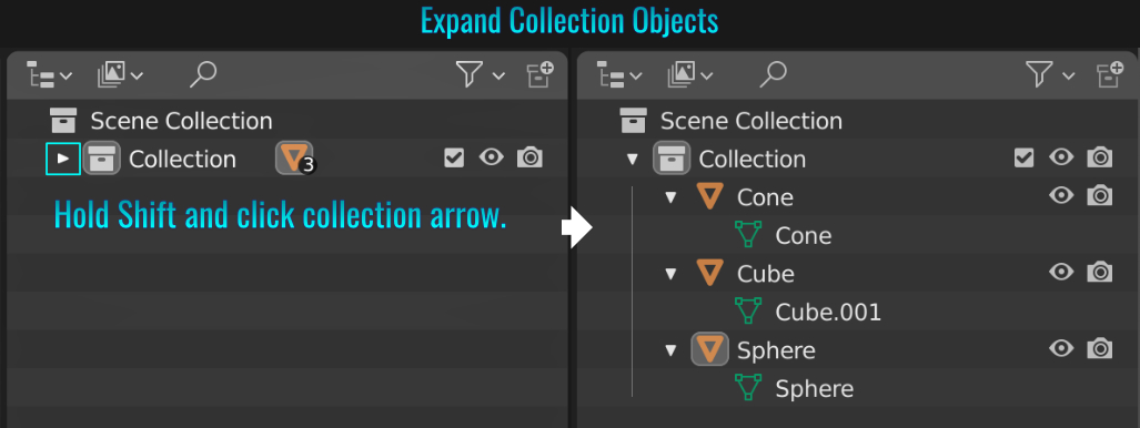
- Evenly Spaced Out Vertices
Sometimes for one reason or another, the alignment of vertex spacing can be off (for example, the spacing of segments on a cylinder). Fear not, as Blender can fix this! First, make sure you have the Loop Tools add-on installed (it comes with Blender). Then select the ring or loop of verticies that contain uneven spacing and right-click and choose LoopTools > Space. Voila! Those verticies should now be evenly spaced out!
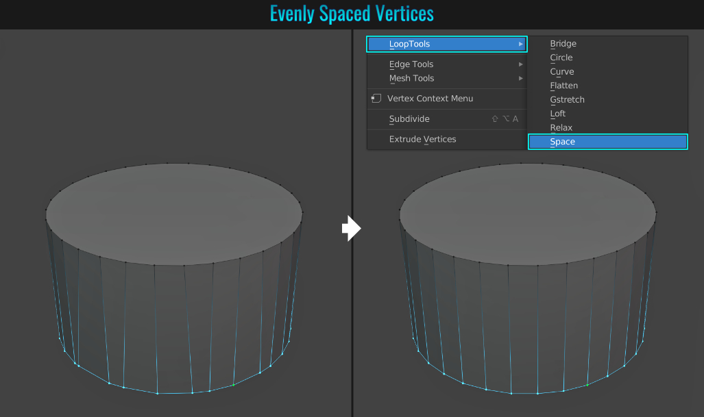
- Using Array & SimpleDeform Modifiers For Radial Array
One quick and easy way to make a radial array of a single mesh for easy modification that will propogate through the others is to start with a plane. Rotate it say on the X axis 90°. Press Control + A (to bring up the Pie Apply Transforms menu) and apply its Rotation value. Next, simply add an Array modifier, followed by a SimpleDeform modifier. Within this deform modifier, choose Bend as the mode, set the Angle value to 360° and the Axis value to Z. Now, back in the Array modifier, simply increase the Count value to the desired setting. From here, it's just a simple matter of tweaking the plane mesh, and everything comes along for the ride! A fast and easy way to create a radial array!
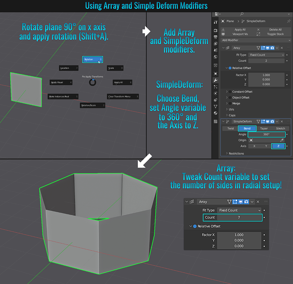
- Changing Default Cylinder Caps
By default, when you add a cylinder primitive, the end caps are triangulated. But within the Add Cylinder panel in the lower left hand corner, you can simply change the cap type by selecting from the Cap Fill Type dropdown menu (your choices are None, N-Gon or Triangle Fill).
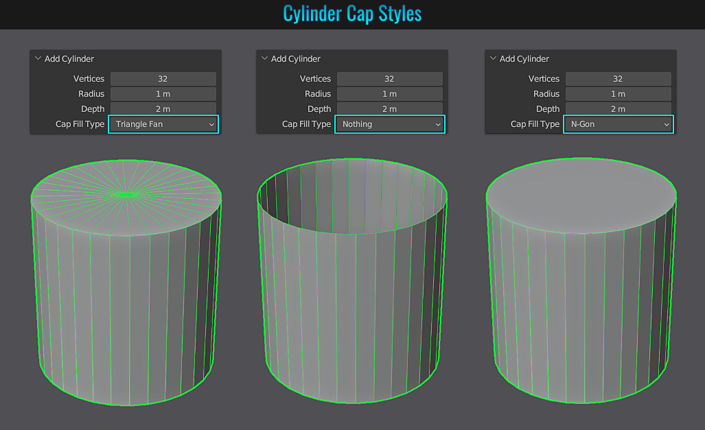
- SimpleDeform Twist Using Restrictions
When using the SimpleDeform modifier, there is no restriction limits - meaning the entire mesh (or selection) is affected. But it is possible to limit its affect! Start by taking a mesh with enough edge/ring loops and apply a SimpleDeform modifier to it (or a selection). Within this modifier, click the On Cage button to hide the mesh cage. Leave the mode on Twist and set the Angle to 360° and the Axis to Z. Finally, open the Restrictions panel and play with the upper and lower Limits values to acheive the desired effects!
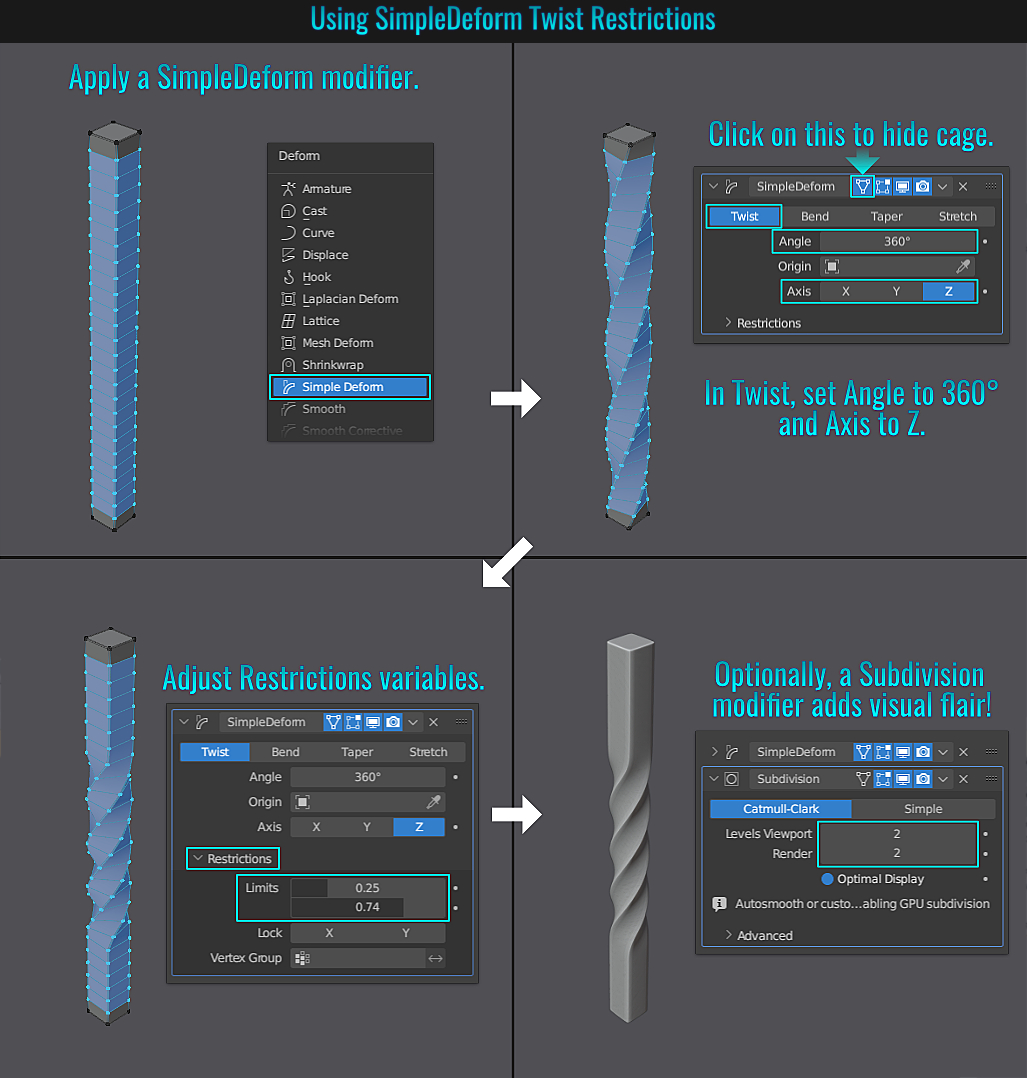
- Adding Edge Loop To Triangle Faces
While on the surface it might seem trivial to add an edge loop to a say a cone, the reality is that since it is comprised of triangles, using Ctrl + R won't work! Below are three different approaches to adding an edge loop to triangle surfaces (using a cone as an example)!
Method 1: Knife tool
Start by going into an orthorgraphic view (like front or side view via Numpad 1 or Numpad 3 respectively) and press K to initiate the knife tool. Next, press A to activate angle snapping. Now press C to set the
knife tool to cut through the entire mesh. Now simply cut horizontally across the cone from one side to the other at the desired location and press Enter to complete the cut! You now have an "edge loop" across the cone!
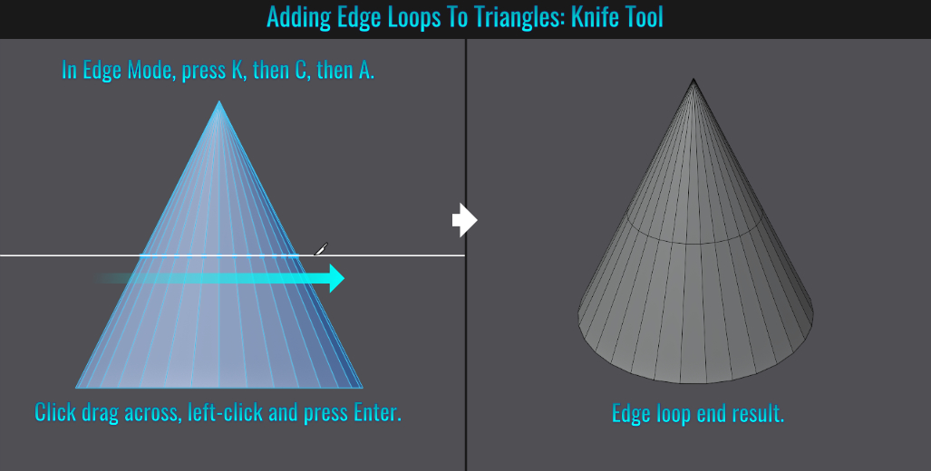
Method 2: Subdivide
A simpler method is to simply go into Edit Mode and Edge Select, then go into x-ray mode (by pressing Alt + Z), click and drag select all the vertical edges of the cone, then finally right-click and choose Subdivide! Now you
have an edge loop!
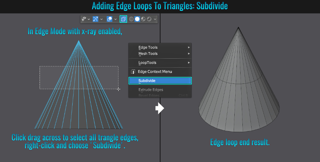
Method 3: Bevel & Slide
This final method makes use of the bevel tool (which will result in an unecessary additional edge loop, but this is easily removed afterwards). Start by select the bottom edges of the cone and press Ctrl + B to activate the bevel tool. Click drag then click again
to get the bevel started.
While the tool is still active, open the Bevel operations panel in the bottom left hand side of the viewport and set the Segement value to 2 and the Shape value to 1. This leaves the original cone's
bottom edges in place and merely adds an extra set of edge loops on either side of it! Simply dissolve the loop on the under side of the cone by selecting it and pressing Ctrl + X, and then select the loop on the vertical edges and slide it (pressing G twice)
to the desired height along the cone and voila! Yet another edge loop!
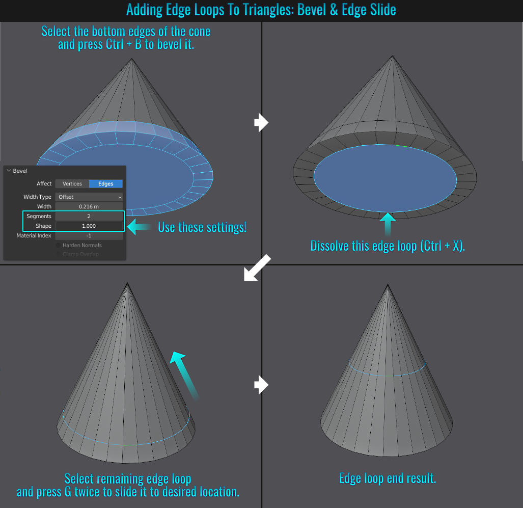
- Blender Using Windows Fonts
When it comes to dealing with fonts in Blender, there is a *gotcha* that you need to be aware of! Once you download a font and unzip it, the normal process is to select the font file(s) in question, right-click and choose Install - this will install the selected font(s) to the
C:\Windows\Fonts folder. You can view these fonts by clicking on the Windows Start button and type in fonts and hit enter. You should see an option for Control Panel Fonts. In here, Windows conveniently displays all fonts installed.
The problem with simply installing a font in this way is that there is a fair chance that Blender won't see it when you look for it in a text-based object! The solution? After selecting the downloaded fonts and right-clicking to bring up Windows file menu, choose Show more options,
then in the next menu, choose Install for all users instead. As a result, Blender will see the newly installed fonts when dealing with text!
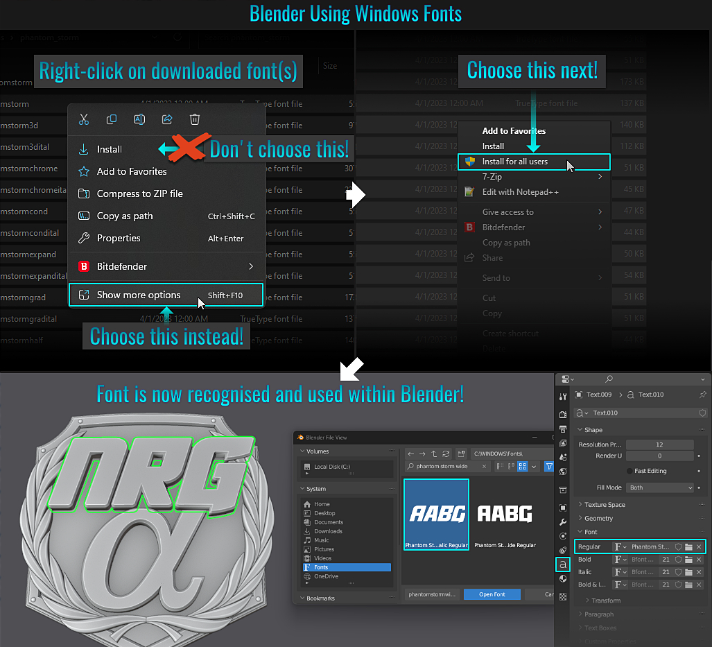
- Different Methods Of Modelling An Arch
As with anything else in the world of modelling, there are many different ways to accomplish a task. In the following examples, we'll look at some of the various methods on how to model a simple arch!
Method 1: SimpleDeform Modifier
With this method, it is important to note that there are two variants that can be employed here. One is using an Empty object, and the other is without. Let's start with the one without! In both examples (as well as the Warp Tool method), an elgoated cube will be the starting point.
So take a cube and in Edit Mode, press S to scale, then press X for the axis and optionally type in something like say10 (or feel free to set a different length) and hit Enter to finalise the scale. Next, hover the mouse
over one of the elongated edges (it doesn't matter which sub-selection mode you're in, be it vertex, edge or face), press Ctrl + R and scroll the mouse wheel to create enough segments for this mesh to bend smoothly! Left click to set the segment count then right-click
(to cancel any positional shift in the cuts and finalize them)!
Note: If you scale the cube in Object Mode, afterwards press Ctrl + A (to bring up the Apply Transforms menu) and choose Scale to apply it! Otherwise, scaling in Edit Mode doesn't require this!
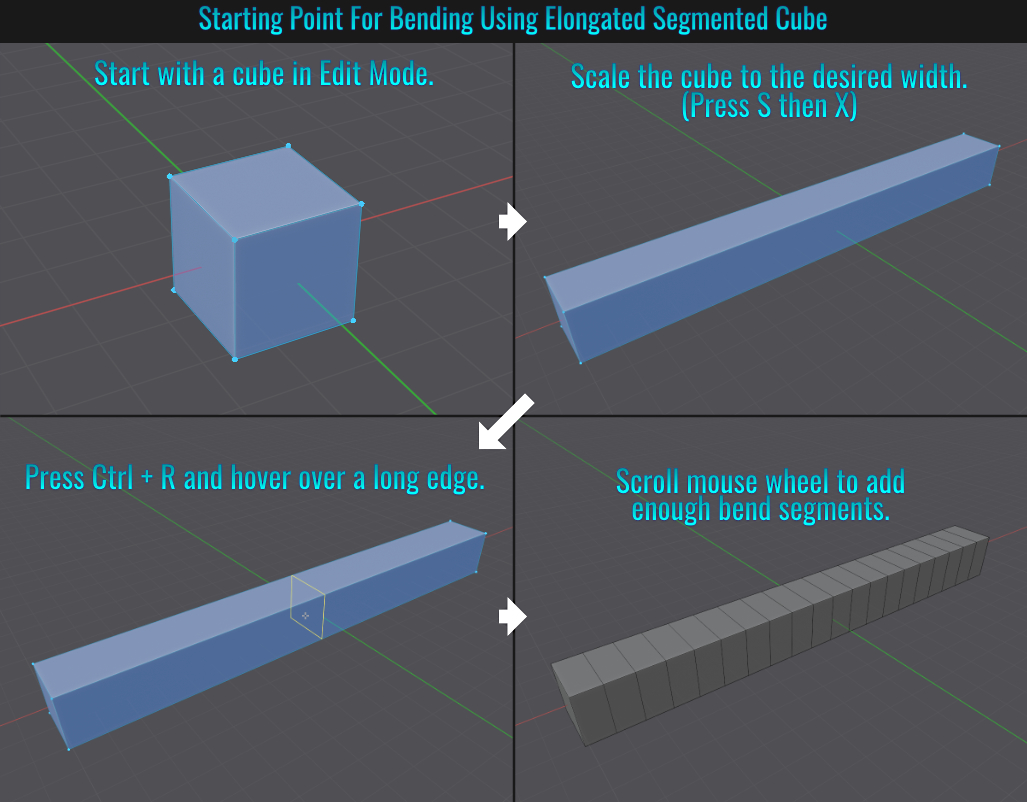
Version A - Without Using Empty Object
Now that we have our elongated/segmented cube in Object Mode, simply head on over to the Modifier Properties tab and add a SimpleDeform modifier. Within the modifier, simply set the mode to Bend, the Axis value to Z and the
Angle to 180°(of course, feel free to choose differently to achieve the desired arch affect you are going for)!
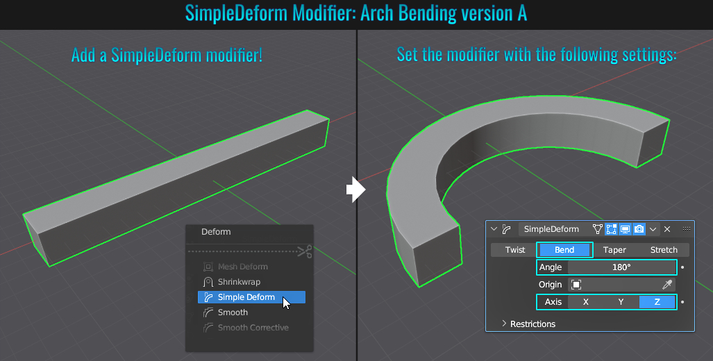
Version B - Using Empty Object
Once again we'll start with the elongated/segmented cube from before. This time, press Shift + A (to bring up the Add menu) and choose Empty > Plain Axis to add one to the scene! Dimensionally, it might be hidden in the cube, so feel free to navigate
over to the Object Data Properties tab and adjust the Empty object's Size value! Select the elongated cube, apply a SimpleDeform modifier and set it as in verison A, but from the Origin dropdown choose the Empty object! The key difference
here is that when you move the Empty object around, it's location in relation to the elongated cube affects the arch's radius (and rotation if you move the Empty object in the x axis)!
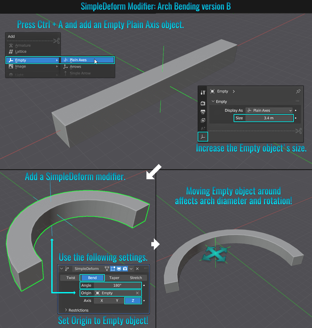
Method 2: Spin Tool
Start with a Plane mesh and enable the 3d Cursor (if you haven't assigned a shortcut for this, you can find its visibility toggle in the Show Overlays drop down menu above the viewport). The Spin tool makes use of this 3d cursor as an offset if you
will. So start by moving the 3d cursor off to the side of the plane by holding down Shift and right-click dragging (additionally/optionally, you can ensure that the Snap settings are set to Increment and enable Absolute Grid Snap for easy and accurate
3d cursor grid movement)!
Once you have the position where you would like it, simply select the plane's face and from within the left hand side toolbar (Press T if it isn't visible) choose the Spin tool. You'll notice a "rotation arc" gizmo set at a
specific axis at the 3d cursor's location. Click and drag one of the gizmo control points to start the spin operation. Next, open up the Spin tool redo panel in the lower left hand side of the viewport. Here, you can futher adjust the Axis, Center, number of
Steps and Angle values for example!
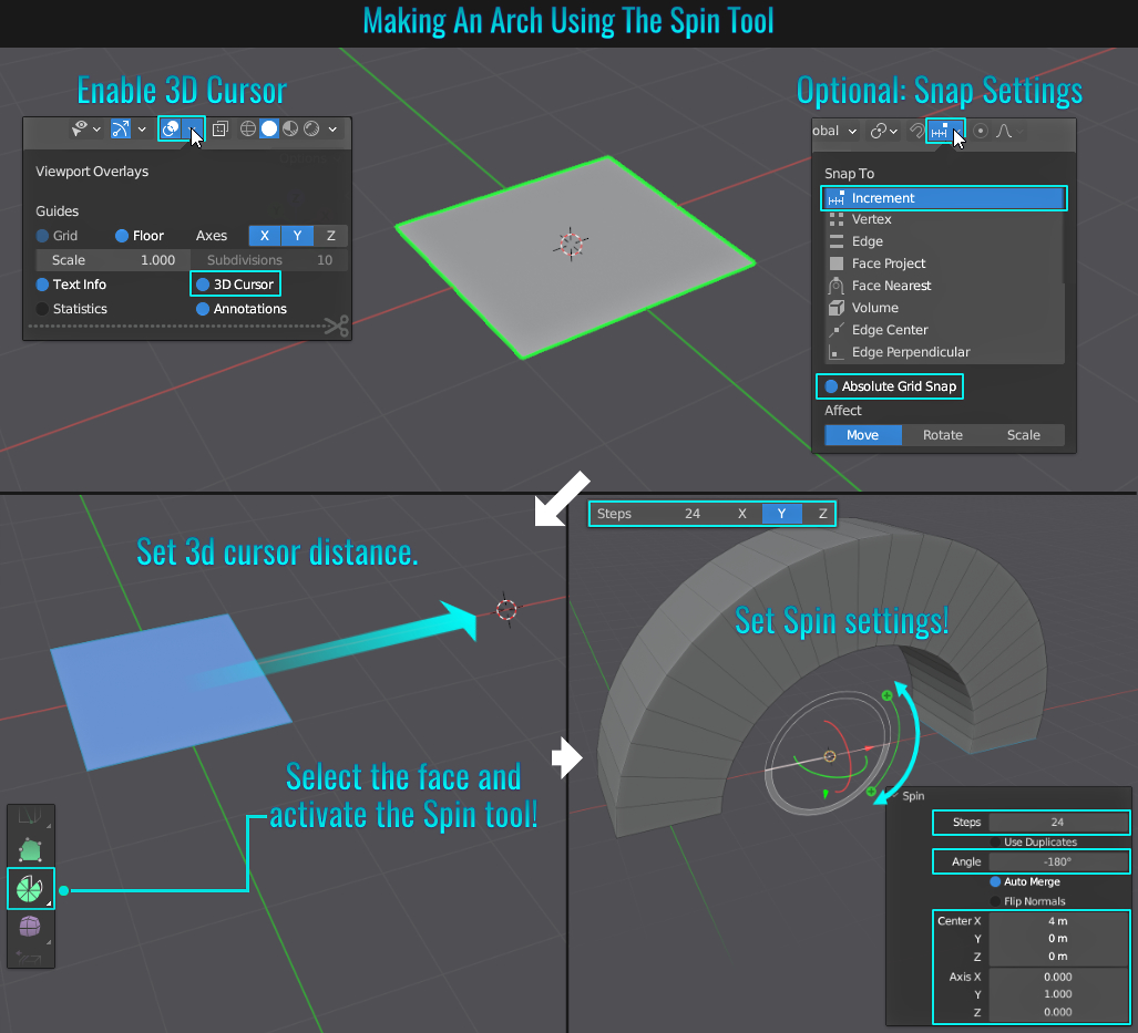
Method 3: Warp Tool
Once again, we'll start with the elongated/segmented cube example from the earliest method. Much like the Spin tool method, we need to make use of the 3d cursor. Unlike the Spin tool method however, this also makes use of the current viewport view. So either place the 3d cursor below the elongated cube
(or raise the mesh itself) to a suitable distance in an orthographic view like the front view (press Numpad 1). In Edit Mode select all of the elongated cube mesh's vertices (or edges) and go to Mesh > Transform > Warp to start the warp operation!
Within the Warp redo panel in the lower left hand corner of the viewport, change the Warp Angle to 180°!
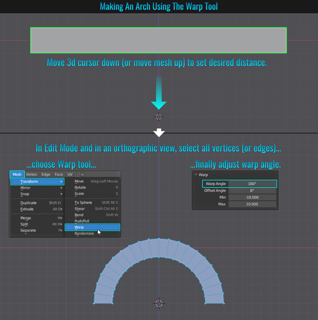
- Select Similar: Polygon Sides
While this is technically a Select Similar tip and could be lumped into Select Similar, I figured this would be more useful as a stand alone tip! Sometimes you might need to find all specific n-sided polygons in your mesh (in this example we'll look
for triangles, but this can be adapted to find any sided n-gons).So with a mesh selected in Edit Mode and in Face sub selection mode:
- if your mesh already has a triangle polygon, simply select it.
- if it doesn't have a visible triangles, simply select a quad, press Ctrl + T (see Triangles And Quads) to create two triangles and select one of those triangles.
Next, press Shift + G to bring up the Select Similar menu and choose Polygon Sides. If you open the Select Similar redo panel in the lower left hand corner of the viewport, you'll notice that by default the Compare value
is set to Equal! Since a triangle was selected, all 3 sided n-gons are selected! This is a fast and easy way to find a specific amount! If you need to find any faces that are greater or less than the selected amount, you can adjust the Compare value accordingly!
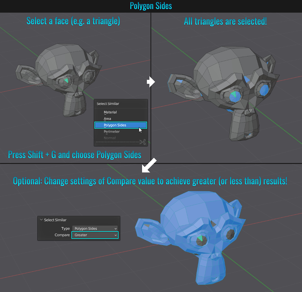
- Select All By Type
There might come a time when you need to select every type of something (in this example, all lights in the scene). The following screesnhot represents a simple scene littered with lights and cubes that could be representative of something more complex. So, instead of manually selecting all the lights for example, the quick and easy way to do this is to go to the top viewport menu and choose Select > Select All By Type > Lights (you can choose from a bunch of different categories depending on your needs!)
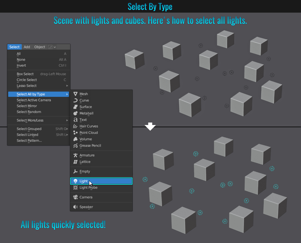
- Hover Over Viewport DropDowns
While not an earth shattering tip by any stretch, did you know that if you left-click on one of the upper right-hand corner viewport dropdown menus (View Object Types, Show Gizmos, Show Overlays & Shading) and simply keep the mouse cursor along those menus, you can click-drag hover over each one, opening the respective dropdown without needing to click it?
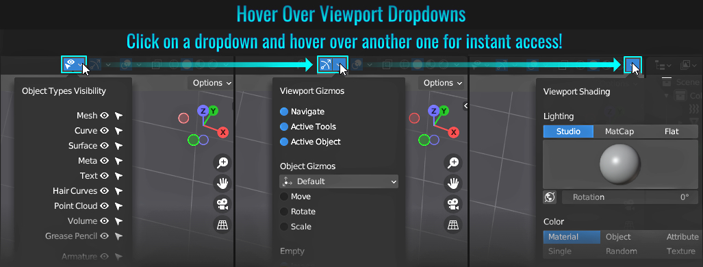
- Alter Bevel Using Modifier & Vertex Groups
Sometimes you might bevel an edge, only needing to alter the "slope" of the bevel on either side of it afterwards. The problem with traditional destructive bevels is that moving any surrounding edges to the beveled effect doesn't alter the bevel itself!
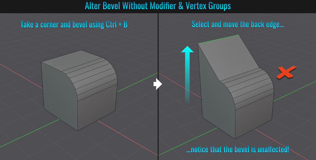
However, we can alter a bevel slope by simply doing the following:
- Select the edge you wish the bevel and from the Object Data Properties tab, click + button within the Vertex Groups panel and then click the Assign button to store this edge's related vertices to it.
- Next, add a Bevel modifier to your mesh. Change the Limit Method value to Vertex Group from the dropdown menu and when the vertex group field appears, choose the group we just created as its value.
- Adjust the bevel width and segments to your liking from within the modifier.
- Finally, select one of the edges surrounding the bevel and move it. Notice that the slope affects the entire bevel itself! This lends to some creative modelling possibilities!
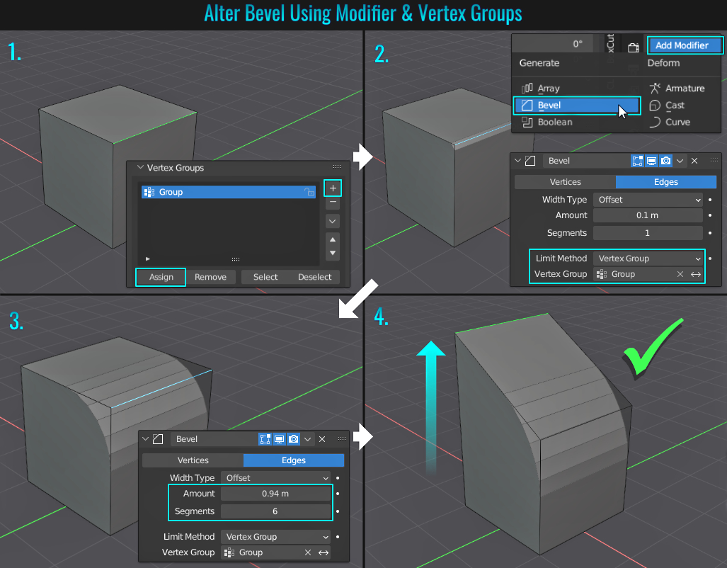
- Select Loop Inner-Region
When it comes to selecting only a part of a mesh, depending on the mesh's sophistication, it could become quite combersome! Luckily, there is a fast and easy way in Blender! While the following example is a simplified one, this method can be applied to more complex meshes as well!
In
Edge Selection mode, start by selecting the base edge loop of the part of the mesh you wish to select. In the viewport's menu along the upper left hand corner, choose Select > Select Loops > Select Loop Inner-Region. All the edges on one side or the other of the selected edge
loop should be fully selected. Finally, switch to Face Selection mode. If the desired selection is inversed, simply press Ctrl + I to invert the selection! See how fast and easy that was?
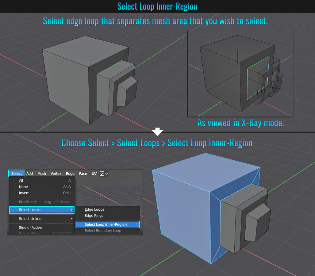
- Subdivision Boundary Keep Corners
When subdividing a mesh using the Subdivision modifier, it is natural that everything gets smoothed out! But depending on the situation, you might not want corners to be smoothed as well. Let's take an example of a flat ribbon (basically an elongated plane with segments) that has this modifier applied. The goal is to have the ribbon smooth, but retain their hard corners. Within this modifier, open up the Advanced panel and set the value from the Boundary Smooth dropdown menu to Keep Corners!
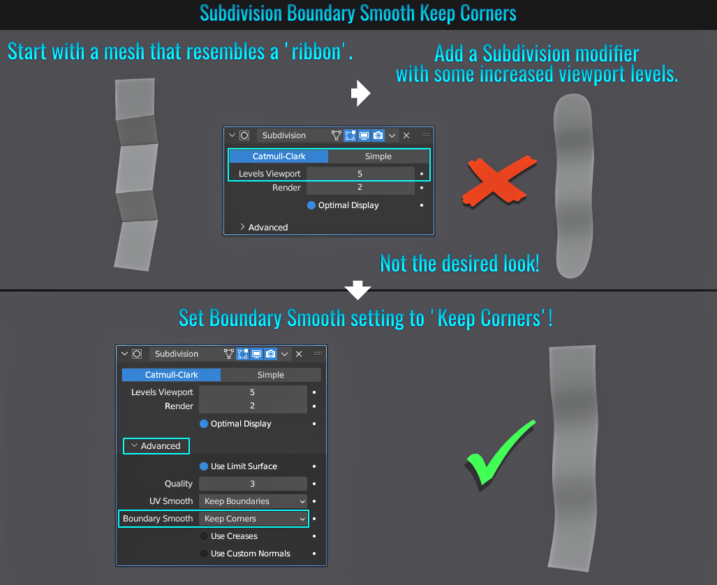
Depending on Blende's settings and monitor resolution, you might find that when you want to select faces while in x-ray mode (Alt + Z) the central selection dots on each face could be too small! Luckily, Blender has a solution for this! Simply go to Edit > Preferences and from within the Themes panel, open the 3D Viewport section and at the very bottom, locate and adjust the Face Dot Size value!
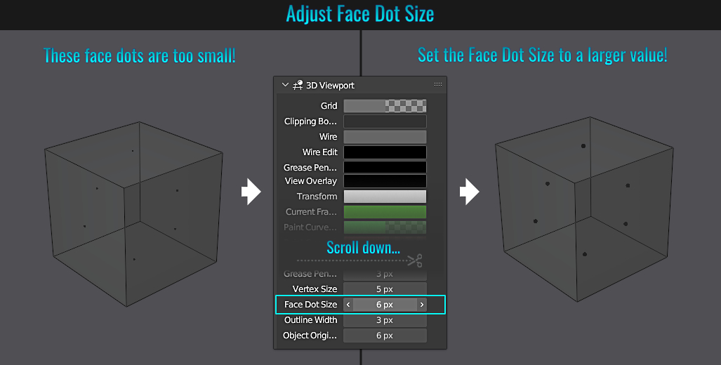
- Shade Smooth Selected Faces
Did you know that you can apply shaded smoothing to only some faces on the mesh? Simply go into Edit mode, select the faces you want, right-click and choose Shade Smooth! Now only those faces you selected will be smooth! This just goes to show that smoothing is not all or nothing globally across the entire mesh!
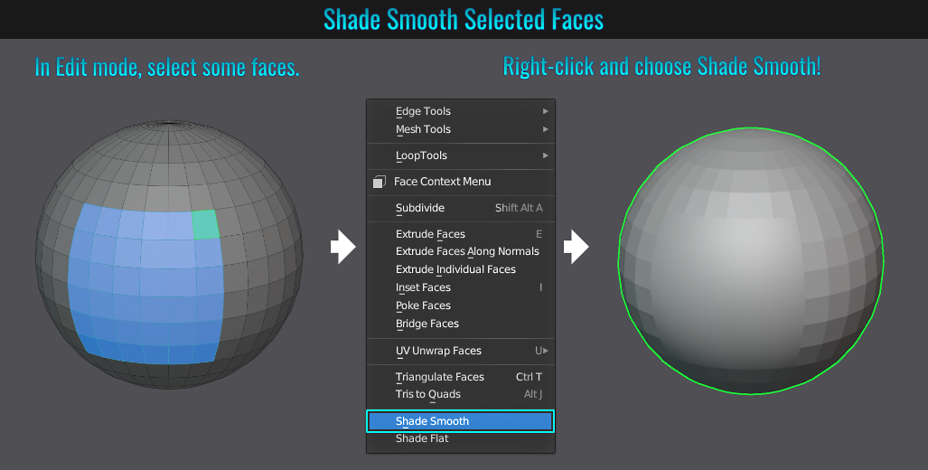
If you need to create a duplicated viewport panel that is an undocked floating window, simply position your mouse cursor over the desired panel's upper right hand corner (your cursor should change to a white cross hair with a black outline), hold Shift and left-click drag in any direction. A duplicated standalone floating window should appear!
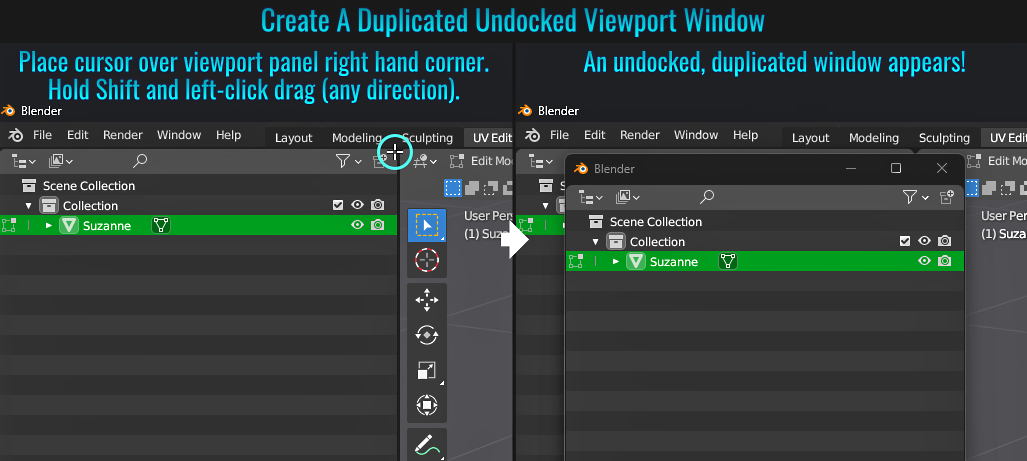
- Metric & Imperial Units
Blender is versatile when it comes to unit measurements. Whether you use metric or imperial, conversions can be done with ease!
Setting Units To imperial
While Blender defaults to metric, you switch
the units to imperial. Simply go to the Scene Properties tab, and from within the Units section, choose imperial from the dropdown menu!
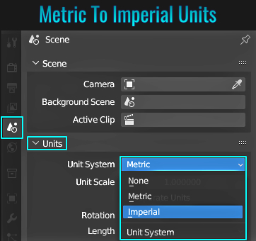
Auto Convert Unit Values
When typing out a value (say in the transform panel), even if Blender's units is set to metric, you can move the mesh using imperial by simply type in the relevant value in feet (e.g. 10') and Blender will move it by that many units (but list the results in metric).
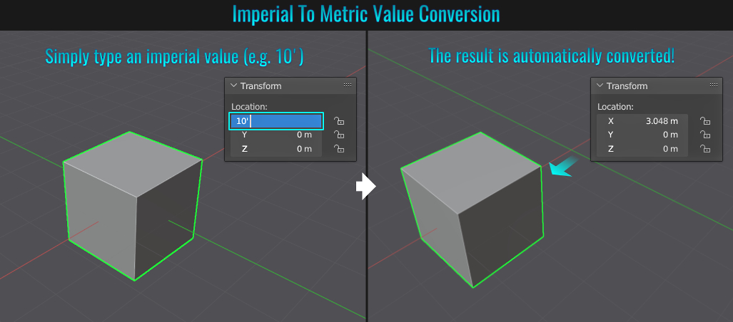
- UV Island Stitching
When wanting to piece UV islands together, there is a quick way to "Stitch" them. Simply start by selecting an island's target edge (or vertices) and press Alt + V. At this point, the corrosponding island that is being stitched to the target should show up as a preview. To finalize the stitching operation, simply press Enter. Donzo!
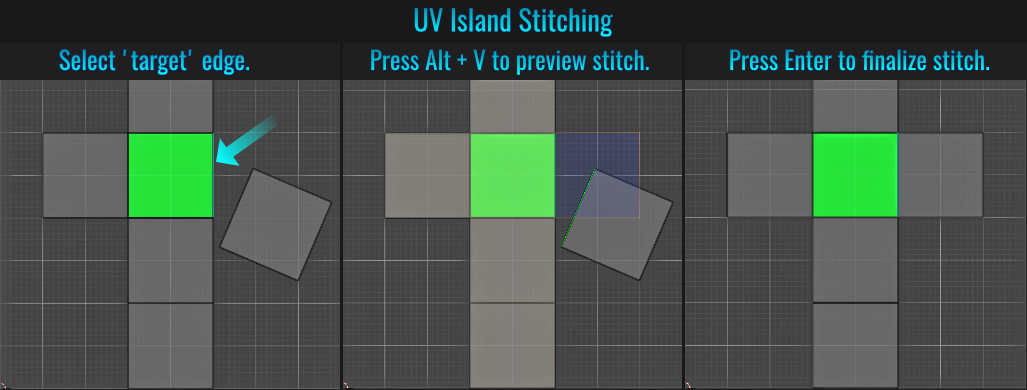
- Marked Seams
When modelling (especially higher resolution meshes), you might want to be able to easily select certain surfaces. Depending on the geometric density, manual selections might prove time consuming and combersome!
There is a quick way to do this however, and all it takes is setting some
certain edges in a way that facilitates this. Start by ensuring you are in Edge mode and going to Select > Select Sharp Edges from the top viewport menu. All sharp edges on your mesh will become selected. The from the Edge menu (or by simply right clicking while
in edge mode to invoke the edge contextual menu), choose Mark Sharp. Now, in face mode, you can simply hover your cursor over any face and when L is pressed, the entire face set within the marked seams will become selected.
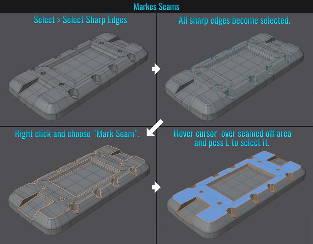
- Multiple Contextual Menus
It is possible to be in more than one selection mode while in Edit mode (i.e. have both vertex and face mode selected by selecting one mode, then Shift clicking another mode). Once more than one mode is selected, right-clicking in the viewports will bring up contextual menus for all sub-selection modes enabled!
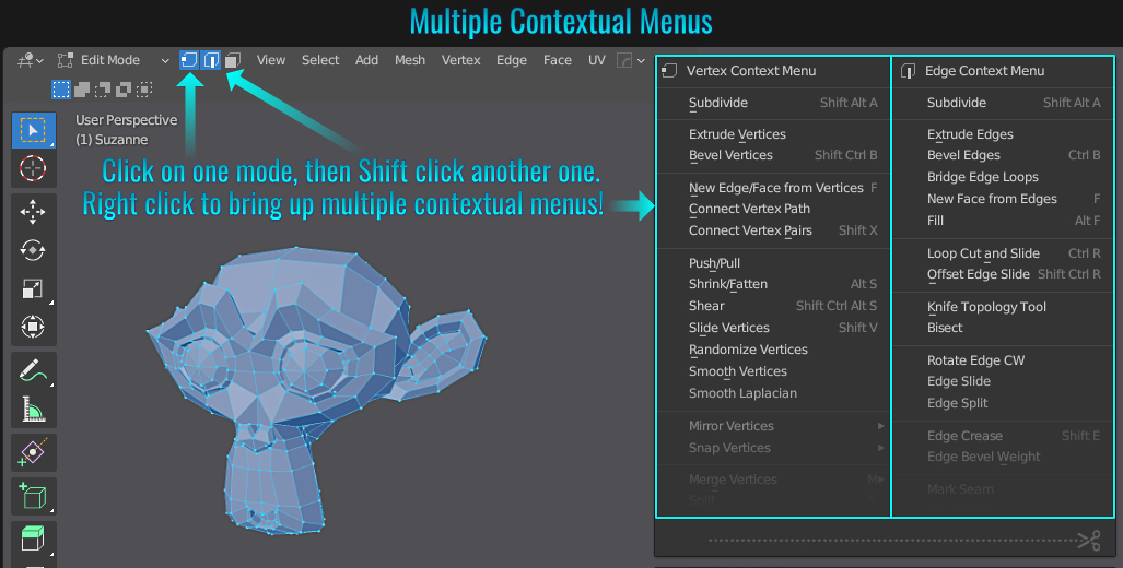
Ever want to have saved view positions without the need of using cameras? There is a way to do this in Blender.
First you need to enable the Stored Views add-on (simply navigate to the Add-ons side panel and search for the term view) and enable it from the list.
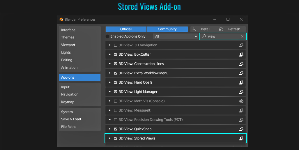
Next, press N to bring up the sidebar, locate and open the Stored Views panel and click the Initialize button. Finally, orbit and zoom in the viewport to frame the subject as you see fit, and from within the Stored Views panel, click on the
Save Current button. A new View slot appears! Everytime time you click on Save Current, a new view slot is created! Simply click on one of these stored view slot cube icons to change the viewport's view to that particular save!
Clicking on the stored view slot's dot will overwrite that slot's view with the current view in your viewport! Quick and easy for multiple views and no cameras needed!
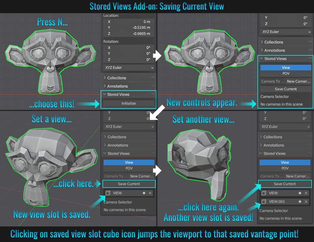
- Moving Parents Or Children
When it comes to moving just the parent or the children, it's relatively easy in Blender. In the following example, the monkey head (Suzanne), the hat and the feather are all children of the Plain Axes empty object (parent).
Moving just the children
To move the children, first select the parent, then press Shift + G (to bring up the Select Group) menu. From here, simply choose Children. Now all the children are selected and can be easily moved. Of course, nothing stops you from manually
selecting each child first and moving them afterwards. This process just simplifies things!
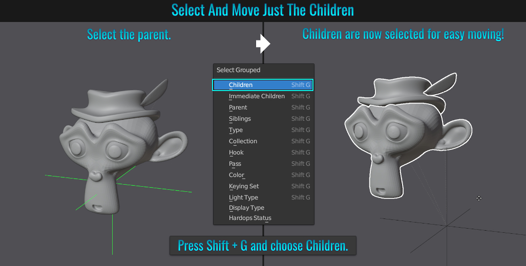
Moving just the parent
To move just the parent without movinmg the children, simply select it and from within the Options dropdown> in the upper right hand corner of the 3d viewport, enable the Parents option. Now you can move the parent without moving the children!
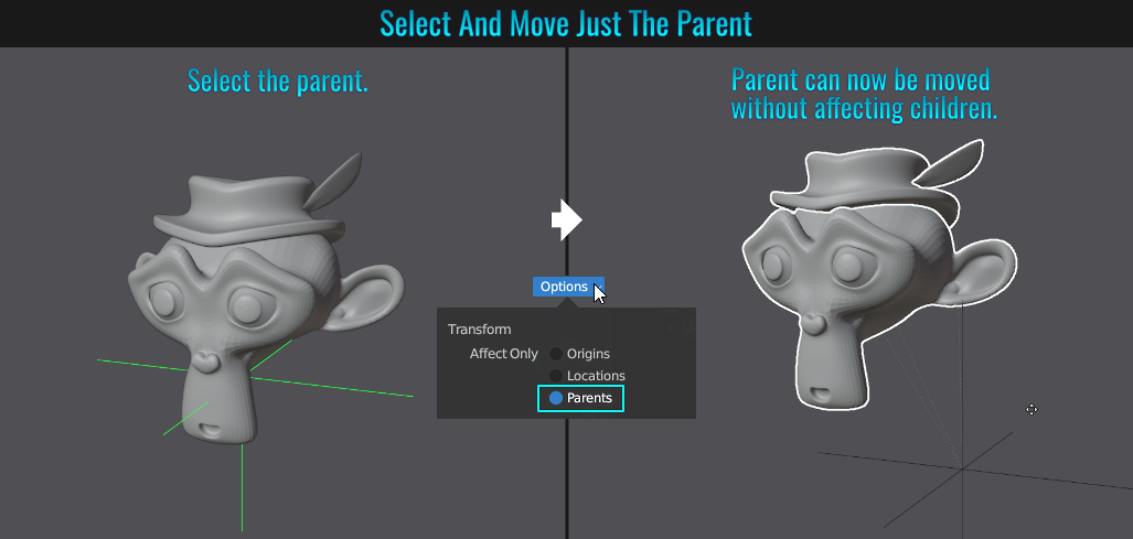
- Selection To Active
Whenever dealing with far scattered objects in the scene and you want to bring them together to a specific object where they are all easily framed and viewable for repositioning, simply select the "target" object (the one that you want to bring the other(s) to), then in the outliner, shift click the other mesh(es) and finally from within the 3d viewport, press Shift + S and choose Selection to Active from the Snap pie menu! Voila! All other meshes are now brought to the target one!
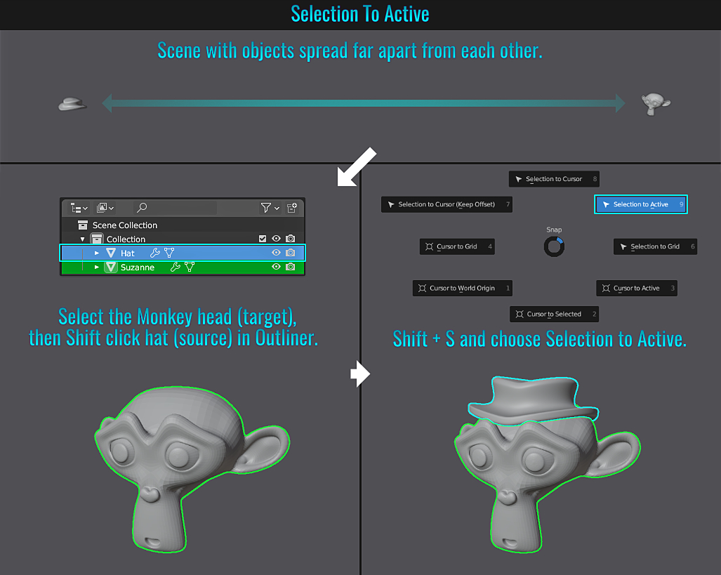
- LoopTools Curve
Basic Curve Usage
One of the included add-ons in Blender is LoopTools (which you'll need to enable if you haven't already done so). This add-on offers a wide array of useful features. This tip will focus on the
Curve tool. The principal idea is simple. With one vertex in say an edge loop positioned differently from the others, you can select this vertex and then some other verts (that you want to remain in place) and when executing the Curve function, all unselected verticies within the edge
loop will be positionally interprolated in such a manner that they form a curve-like visual!
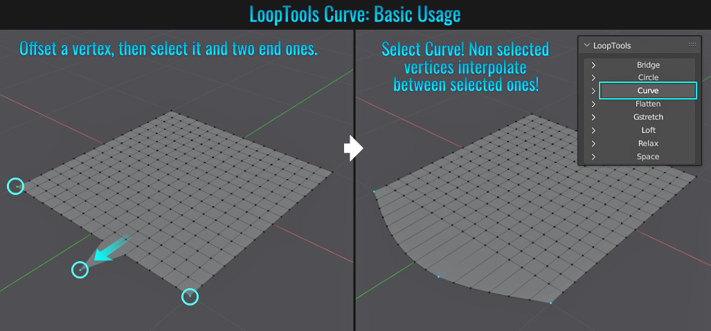
It is important to understand two things regarding the curve function:
1) only unselected vertices are affected (so consider selected vertices as "pinned" in place).
2) If there are only vertices selected within the same edge loop, only unselected vertices between those selected in that loop are affected.
Curve Modelling Usage
The curve tool can by extension be used to help in modelling hard surface assets. Continuing from the example above, let's create curvature to the entire boundary form! Repeat the same basic usage steps as before but on each boundary edge loop (selecting and moving a vertex, then selecting it and the end
verts and once again choosing Curve - this can be accessed via right-clicking and locating the Curve option from the LoopTools menu or by pressing N to being up the side bar and from within the Edit tab, opening up the LoopTools menu
and choosing Curve from there).
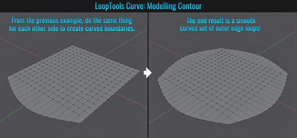
To give this panel equally spaced out edges, simply select one of the outer edge loops (could be in vertex or edge mode), then add the central edge loop to the selection, and finally add the last outer edge loop. When the Curve tool is applied, all the edge loops flowing in that orientation become evenly spread out! Now rinse and repeat with the outer and central edge loops but going in the opposite axis direction! Voial! Evenly spaced out geometry spanning the entire panel mesh!
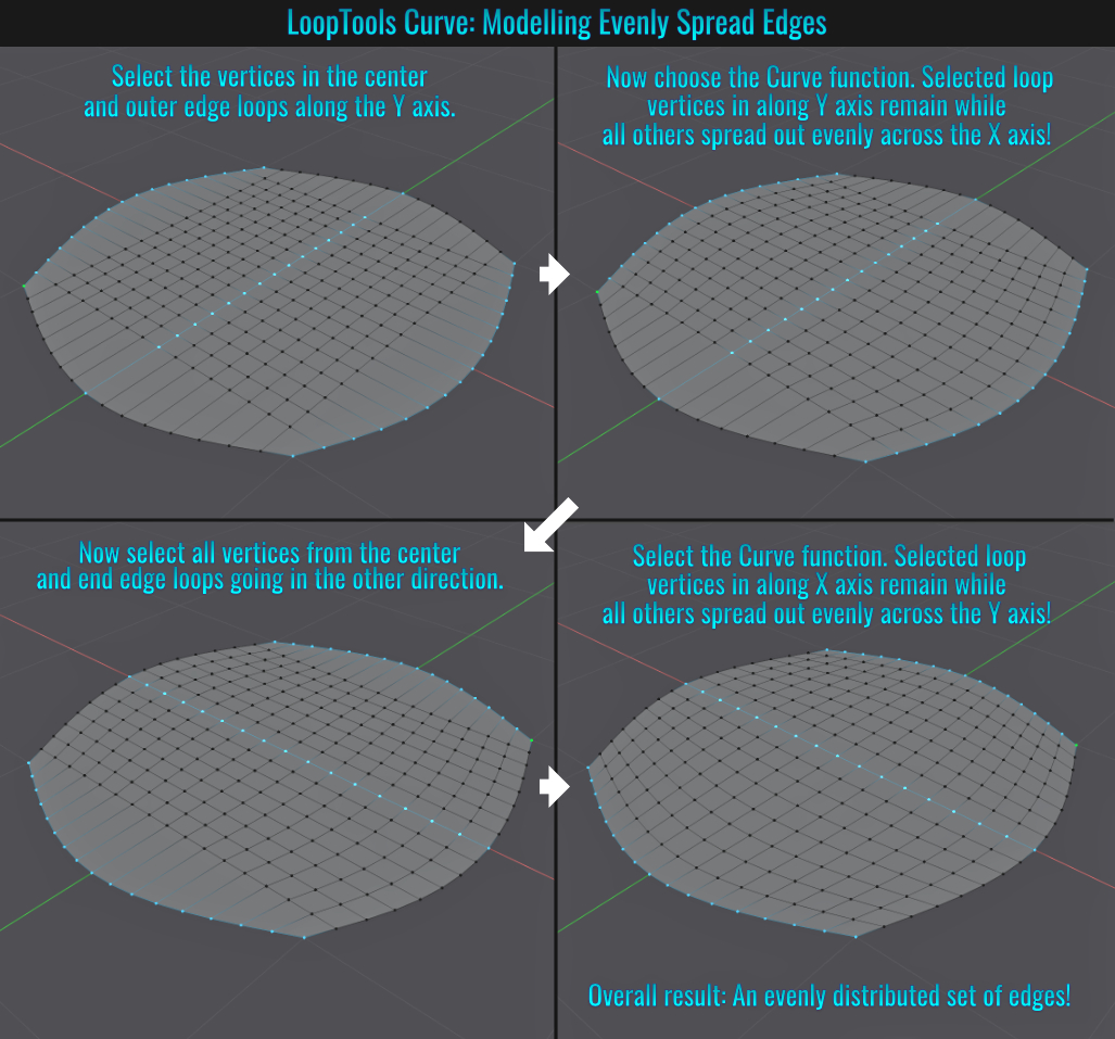
To add a general curvature to the entire surface, the most common go-to solution would be to select and central vertex, then enable the proportional editing tool (by pressing O) and then press say G and then Z to constrain it to the Z axis and pull that central vertex
upwards while adjusting the size of the falloff via scrolling the mouse wheel. The problem here is that while you will create a smooth overall curve, you will also affect the position of the boundary vertices in the process!
Let's look at how to create a general curved surface (without
affecting the boundary vertices) using, you guessed it... the LoopTools Curve tool!
First adjust the central vertex to the desired height. Then, with it still selected, select both end vertices in that edge loop and choose Curve again. The initial result will be
a row of vertices that interprolate between the central and end vertices! Next, select that entire curved edge loop as well as the entire end edge loops on either side and once again run the Curve tool!
The entire surface now contains a smooth interpolated curve without affecting the
boundary vertices!
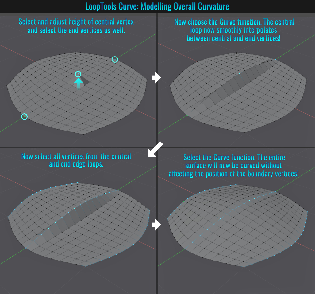
To add a crease, simply select and adjust the height of one of the vertices and then select another vertex along the edge loop where you want the crease to end and once again choose Curve. Additionly, you can adjust the Influence value slider to diminish the curving effect!
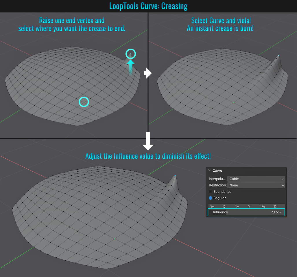
Curve Repair Curvature Usage
Not only is the Curve tool useful for modelling curves/creases, it can also be used to make any repairs to a curved surface (in the event you say accidently moved a vertex or simply decided later on that this is not a desireable visual and feel the need to "revert" the offending
vertex/vertices) to bring the curved surface back to what it was initially!
To do this, simply select the offending vert(s) in question, then press Ctrl + I to invert the selection. Finally, right-click and choose Looptools > Curve and watch the surface
automagically repair itself (note that the Influence slider will always be set to what you last adjusted it to, so you might need to slide this back to 100% to ensure the repair is accurate)!
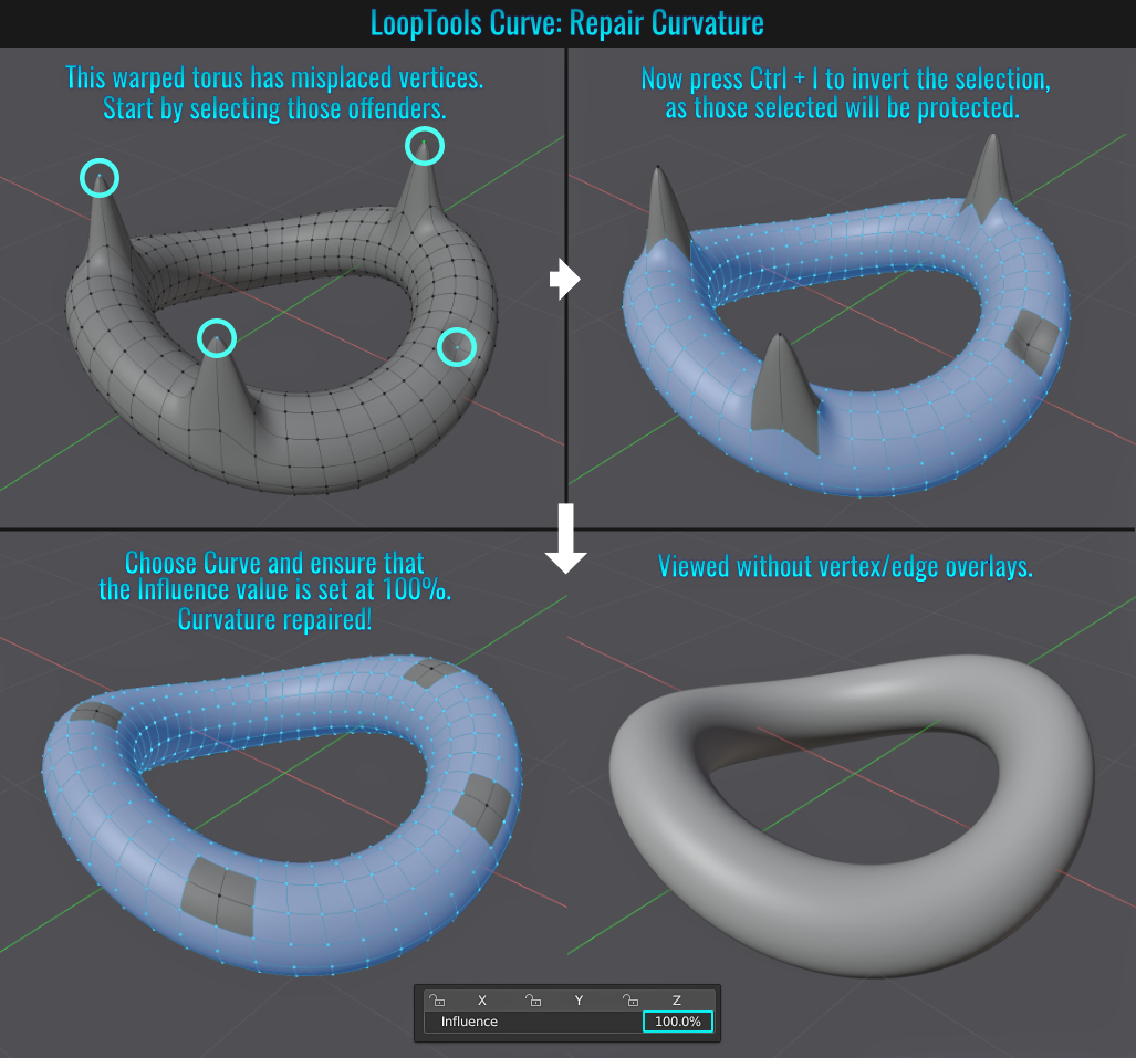
- Extrude To Quickly Create Forms
While it seems like a no-brainer to use extrudes to extend something, this tip is more about making use of extrusions to create things like capsules or elongated chain links with minimal fuss!
Making A Quick Capsule
Lets start by looking at how to generate a capusle from a standard sphere relatively quickly. Press Ctrl + A to bring up the Add menu and choose Mesh > UV Sphere. Next, press Alt + Z to go into x-ray mode and select
half of the sphere in face mode. At this point, most people would probably separate the selection, move it, re-attach it and then select both sets of open boundary edges and bridge them. This is simply too many steps! Instead, simpy press E to extrude and then press the desired axis
constraint key (in this case, X) and move the selection over! That fast and simple!
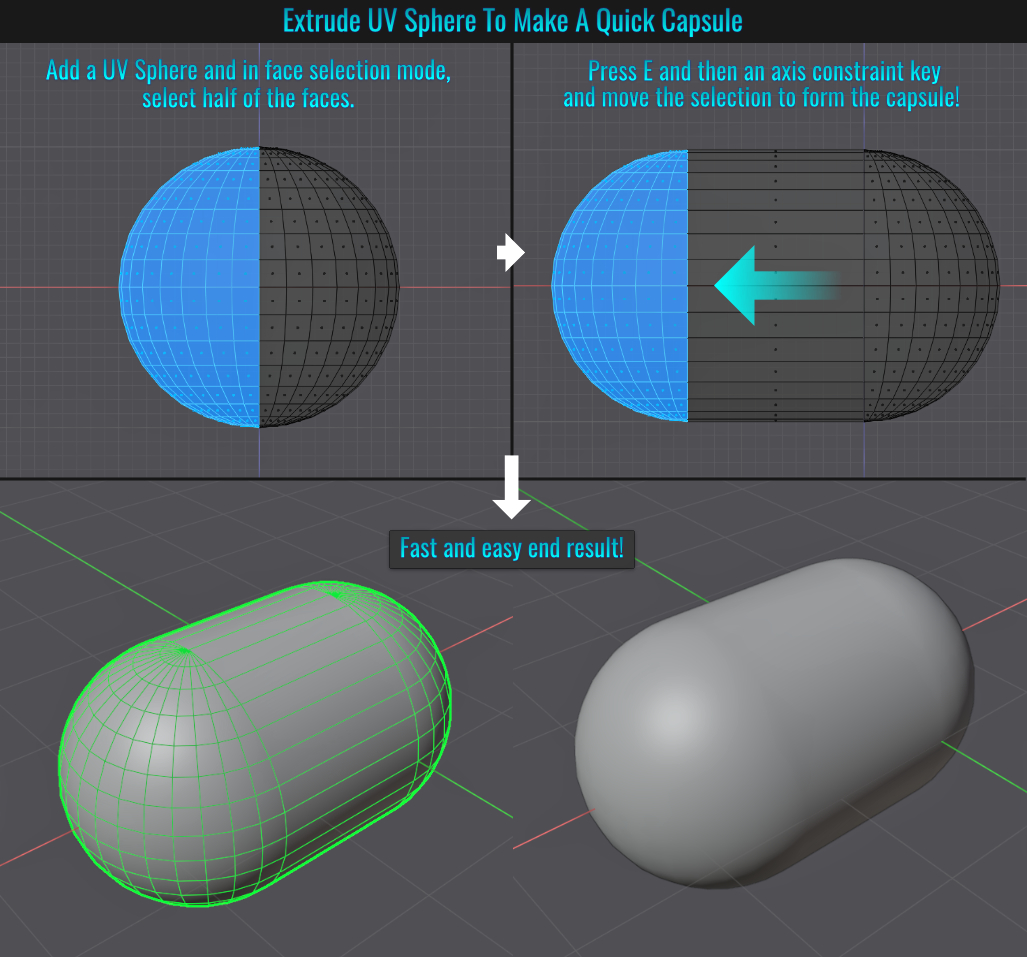
Making A Quick Chain link
Start by once again pressing Alt + A to bring up the Add menu but this time choose Model > Torus. Again in x-ray mode
(Alt + Z), select half of the torus, then press E and follow it with the axis constraint key and drag to form the chain link! You can stop here and be done with it, but if you wanted to make a more rounded rectangular link, simply select the entire bottom set of faces,
extrude and move downwards! Once again, a fast and easy method of creating forms by simply extruding portions of them!
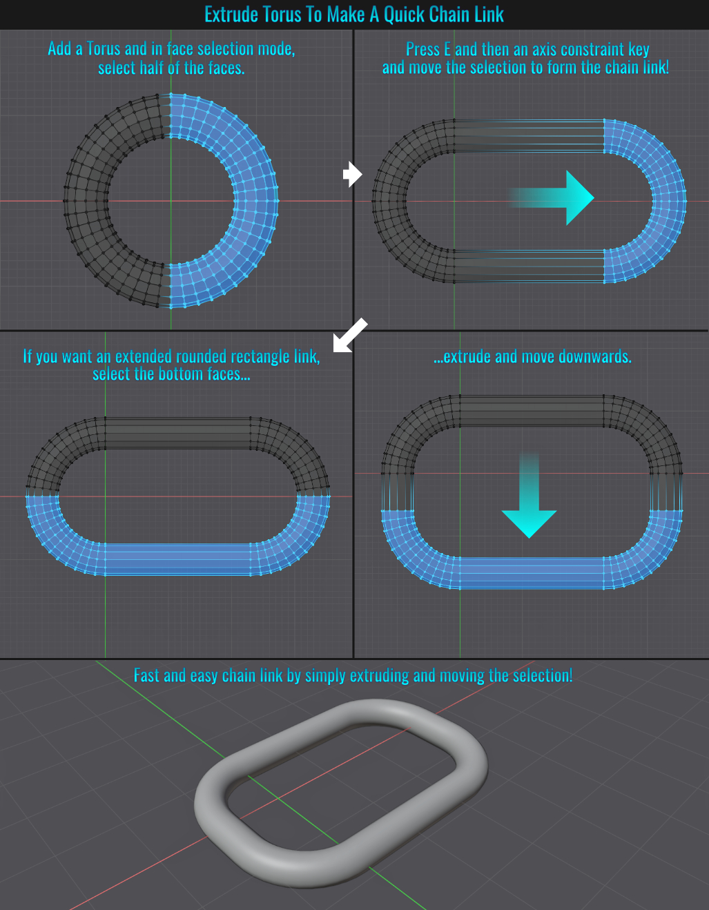
Did you know that you can change the style and size of an Empty object after you have added one to your scene?
Change Empty Style
Simply select the Empty object in question and from within the Data Object Properties tab, within the Empty panel, change the Display As dropdown menu to a diffent Empty object style!
Change Empty Size
Also within the Empty panel is a Size field that can be adjusted. But you can also access this by right-clicking the selected Empty object within the 3d view and choosing Adjust Empty Display Size and simply dragging your mouse left or right (to make it smaller or larger
respectively)!
- Extrude Dissolve Orthogonal Edges
Did you know that while extruding faces that result in other faces being non-manifold and while the tool is live you can simply enable the Dissolve Orthogonal Edges feature to clean things up?
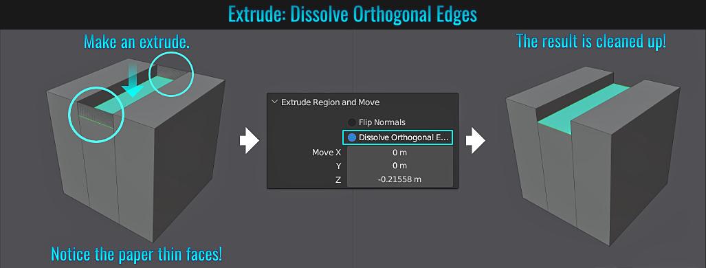
- Face Project Snapping
One of Blender's useful (but probably lesser known) snapping features is the ability to snap a selection from a source mesh to the surface of a target mesh! The idea here is to have a source mesh's selection orthographically view-aligned with a target mesh and snap those to the target's surface!
Start by going to the top snap menu (the dropdown menu right next to the magnet icon) and set the snapping mode to Face Project and ensure that Project Individual Elements (found near the bottom of this dropdown) is enabled. Also ensure that the snap option
itself is off (this will make toggling in and out of snapping much faster!)
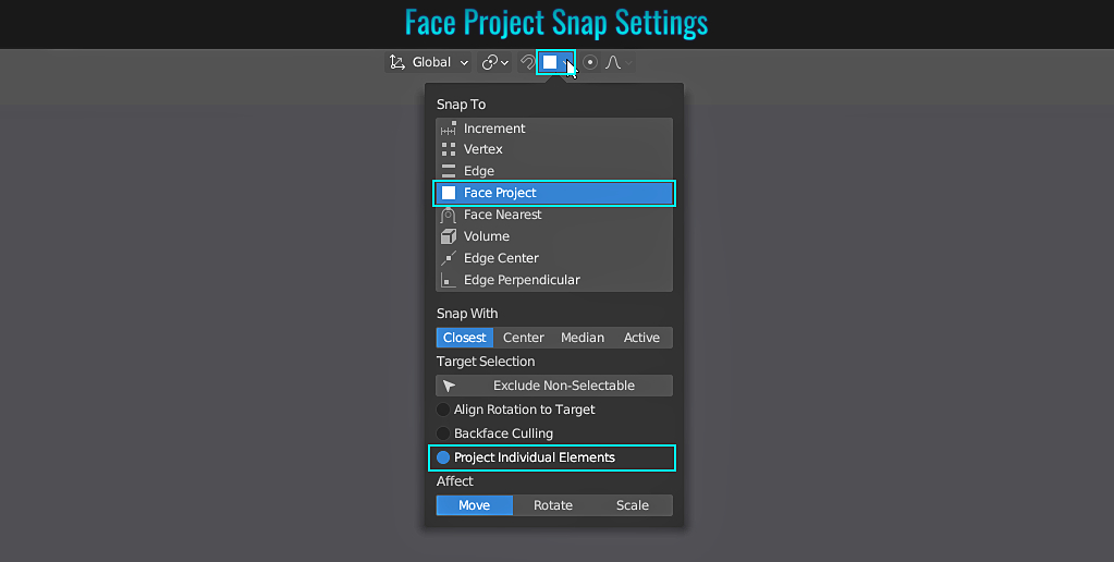
Next, on the source mesh you wish to snap from, either:
- select the vertices you do not wish to be affected and press H to hide them. Then press Ctrl + I to invert the selection (so only the remaining vertices you wish to snap are visibile and selected) -or -
- select the vertices you do wish to be snapped, invert and hide the others, then invert the selection again so that only those initially selected vertices are visbile and selected.
For the following example, we'll use the first option, but this really is case by case dependent. Go with whichever is easiest!
Next, ensure you are in the appropriate orthagraphic view (front/back, side, or top/bottom) as the face project feature is
view dependant! Press G to enter grab mode. Finally, press and hold Ctrl (to temporarily enable snapping), then left click and release Ctrl. Voila! The selected vertices should be snapped to the target mesh's surface! Finally press
Alt + H to unhide the unaffected vertices from the source mesh. Done!
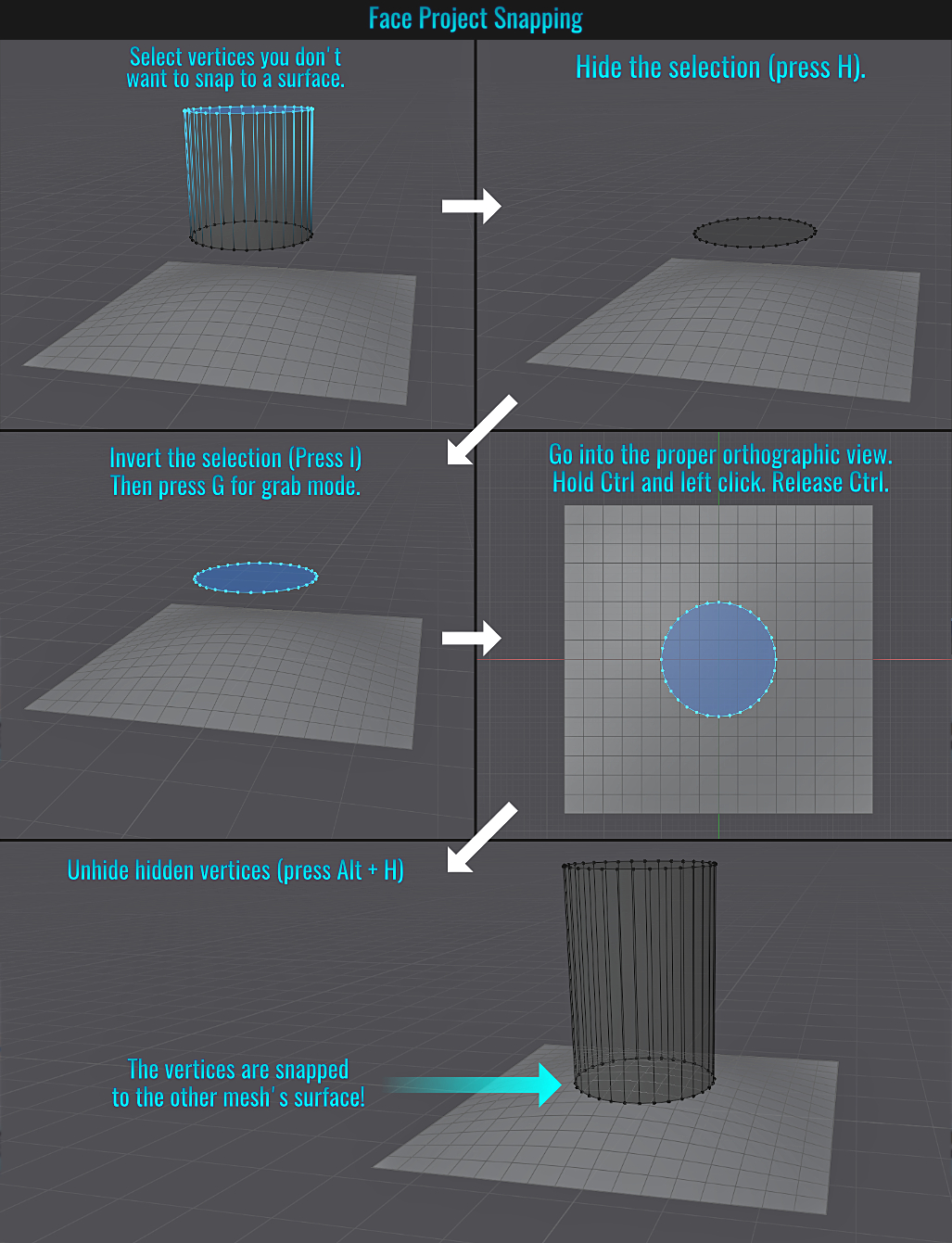
- Composition Guides
Camera composition is important in framing the shots for your renders! Blender has the ability to display a variety of composition lines to meet the majority of compositions out there! With a camera selected, simply go to the camera Data Object Properties tab and from within the Viewport Display panel, open up the Composition Guides sub panel. Here, you will find a good amount of different compositional lines to choose from that are overlaid within the camera view!
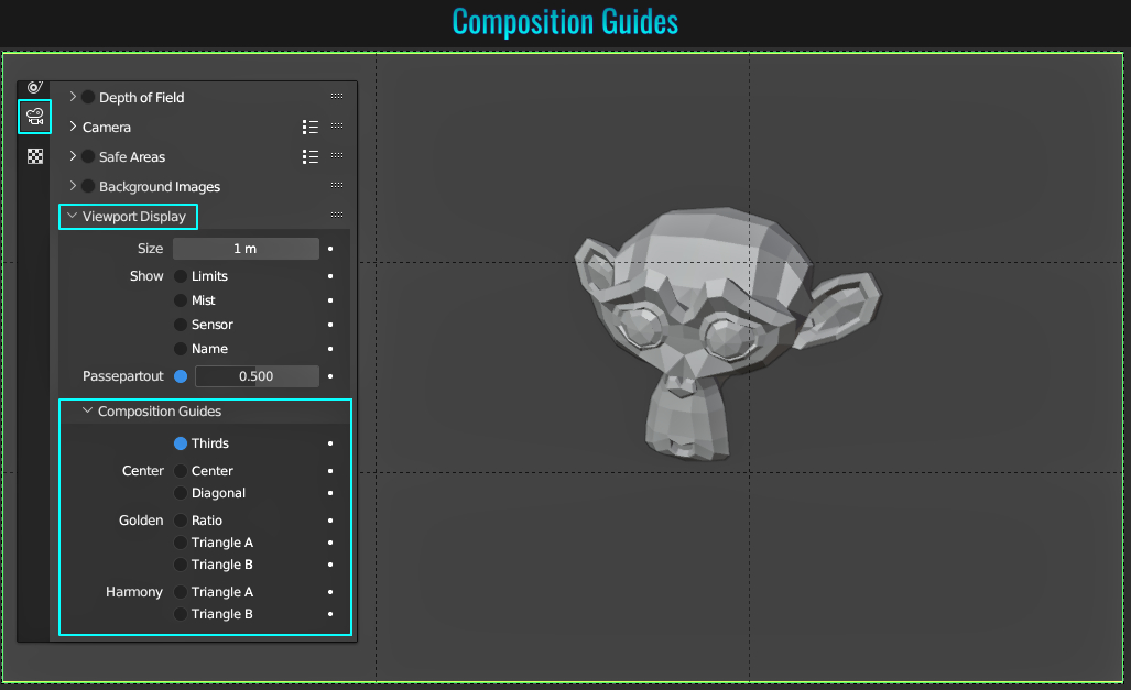
Did you ever want to render what's displayed in the viewport without a camera? You can! Simply ensure that Eevee is the chosen rendering engine, and from within the 3d viewport menu, go to View > Viewport Render Image. One caveat here is that the resulting render window displays everything, meaning things like floor grid, wireframes, empty objects, etc... So if you don't want them visible, you'll need to do some initial setup prior to rendering (you can click on the Overlays dropdown menu button along the upper right-hand corner of the viewport (or alternatively press Shift + Alt + Z) to disable these kind of visual elements quickly).
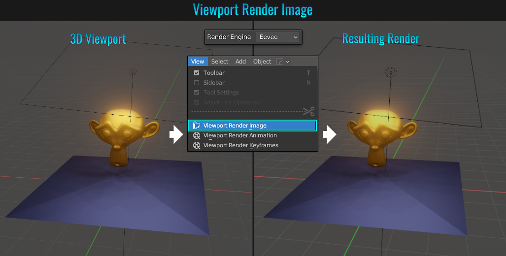
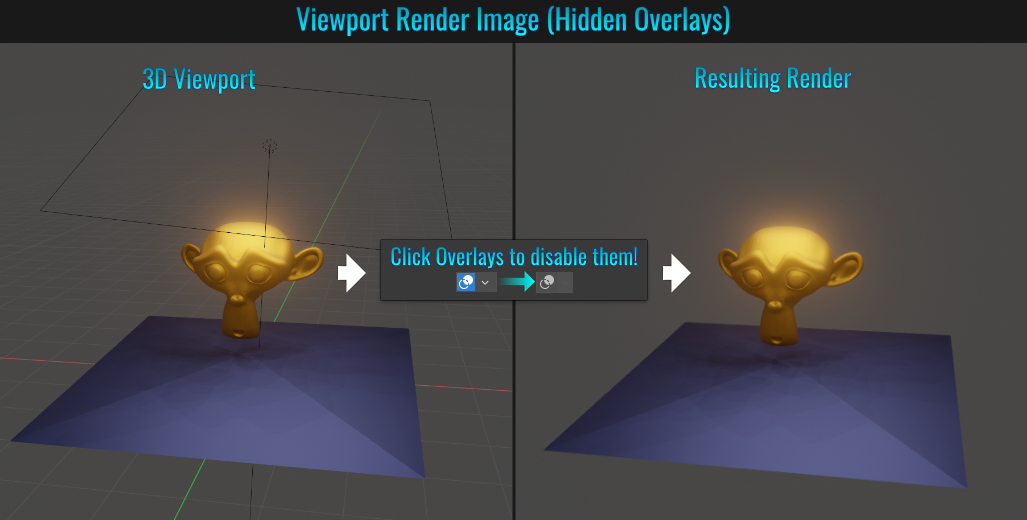
- Join Branching Node Noodles
Whenever working in a node graph (be it shaders or geometry nodes), there might come a time when a single node is connected to multiple others and as a result, you'll want to better organize this. Luckily, it's pretty easy to join multiple branching noodles! Just hold down Shift and right-click drag across the noodles you wish to join and voila! This newly added join point can now connect to other nodes! To move this joined point around, select it and press G! As a side note, it's also possible to add a Reroute node in the editor (which shows up as the join dot) which can then be connected to different nodes!
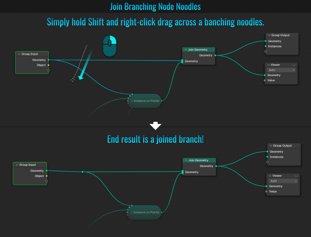
- Orientate And Center 3D Cursor To Selected Face
Orientating and centering the 3d cursor on a face is not difficult (just requires a few short steps).
- In Edit Mode, select the desired face on the mesh in question.
- From within the viewport left hand tools (press T if it isn't visible), select the Cursor Tool (just below the Select Box tool).
- Press N to bring up the right-hand viewport panels and from within the Tool > Active Tool panel, enable Surface Project and choose Geometry from the Orientation dropdown menu.
- Click anywhere on the face to set the 3d cursor's orientation to match. Then press Shift + S (to bring up the Snap pie menu) and choose the Cursor to Selected option (of course, centering the 3d cursor is optional).
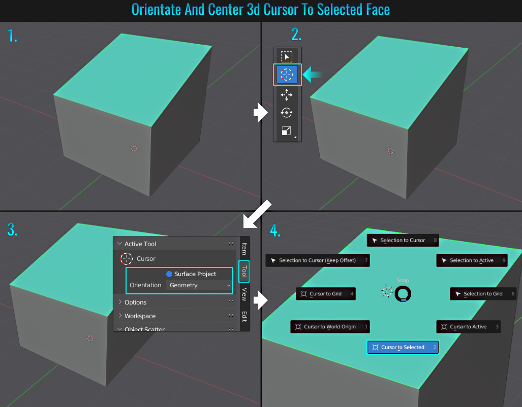
While inserting a primitive places it in the 3d cursor's location, this is useful for changing it's orientation (once a primitive is placed, open the bottom left hand redo panel and change the Align dropdown menu from the default World setting to 3D Cursor!)
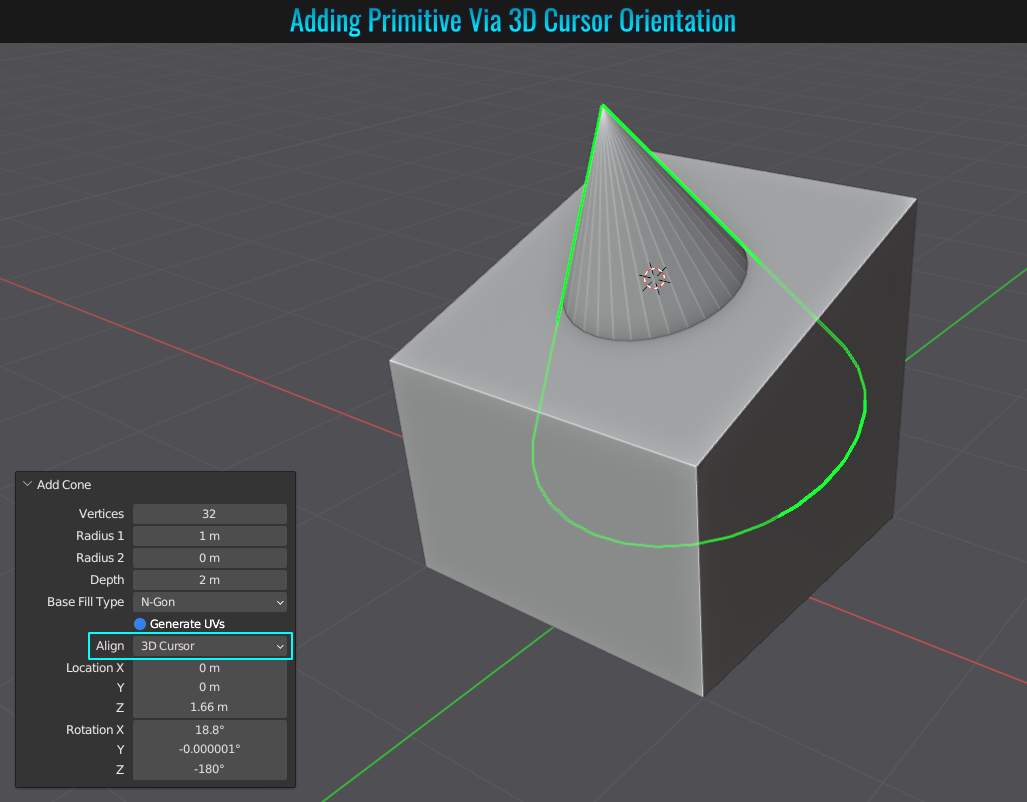
- Blender SimpleDeform Bend Correction
One Blender annoyance is the SimpleDeform modifier (more specifically, the Bend mode within it!) Here is a basic observation... If you add a plane and scale it along the x-axis (then add enough deformation segments and apply scaling via pressing Shift + A and choosing Scale), then add a SimpleDeform modifer, select the Bend mode and choose to bend the mesh in the z-axis, you'll find that the mesh bends as expected.
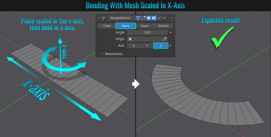
Alternatively however, if the plane was scaled in the y-axis instead and then everything else is repeated, you'll have a nasty result!
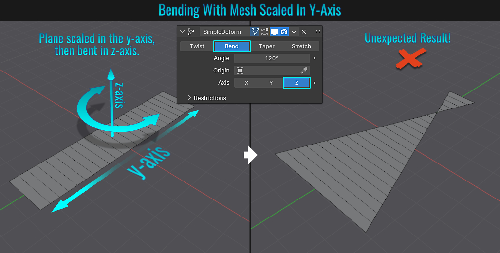
The solution here is simple. With the SimpleDeform modifier still set to bend on the z-axis, simply rotate your mesh on the z-axis by 90 degrees (press R then Z then type 90 and hit Enter), finally press Shift + A (to bring up the apply menu) and choose Rotation to apply it! Now the mesh should bend as expected along the z axis. From here, you can re-rotate the mesh back into its original orientation (without applying the rotation again, otherwise the unexpected bend result will return!)
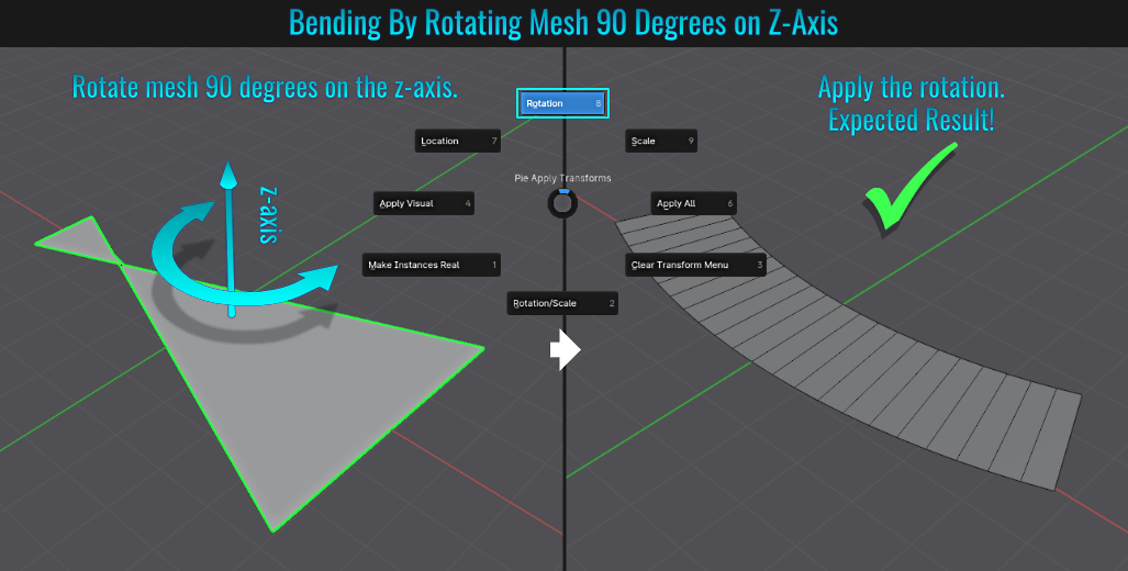
- Auto Mirror Add-on
When only wanting to modify one half of your mesh and seeing the changes reflected on the other half, the mirror modifier is the obvious weapon of choice here. However, if you simply add this, you are missing out on some additional functionality that the Auto Mirror add-on
provides (this is included with Blender but needs to be enabled in the preferences first)!
Once enabled and with your mesh selected, simply press N to bring up the right hand side panel in the viewport, and under the Edit tab, locate and open up the Auto Mirror
panel. The information here differs from the traditional mirror modifier in a couple of ways, like whether to mirror in the positive or negative axis (which could be handy in determining which side of the mesh you prefer to work with), along with a threshold (a range that collapses vertices
along the central axis). There's also the ability to enable Toggle Edit among others! Basically, you can view these options as complimentary to the traditional mirror modifier, as once you set everything up and click on the AutoMirror button, the traditional
modifier is also added! Features from both the add-on and the modifier pack a complete punch!
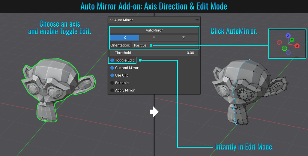
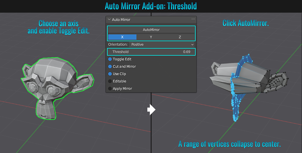
- Adjust Multiple Modifiers At Once
Adjusting the same value on multiple identical modifiers across different meshes is actually quite simple! Select all meshes that you wish to modify, open the modifier in question and hold Alt while adjusting a value! Notice that same value in other modifiers adjust as well ( this doesn't work if you are using Enamble 3 Button Mouse in the Mouse section of the Input panel within Preferences!)
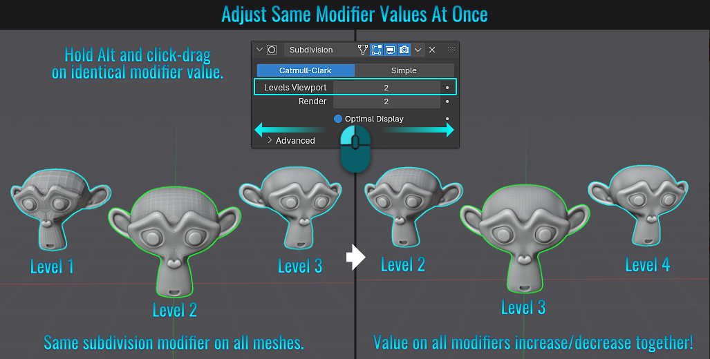
- Isometric Camera Settings
Making a camera isometric in Blender isn't complicated:
- Create a camera (press A and choose Camera from the Add menu), select it and press Numpad 0 to enter the camera's view and roughly frame the scene.
- From within the camera's Data Properties tab, change the Lens panel's Type dropdown to Orthographic.
- Press N to bring up the viewport's right-hand side vertical tabs and from within the Item tab, enter the following for the Transform's Rotation values:
X: 54.7°
Y: Leave this value alone.
Z: 45° or -45° (depending on the view's desired orientation).
- Back in the Lens panel, adjust any additional parameters (like Orthographic Scale, Shift X & Y) to properly frame the camera more accurately!
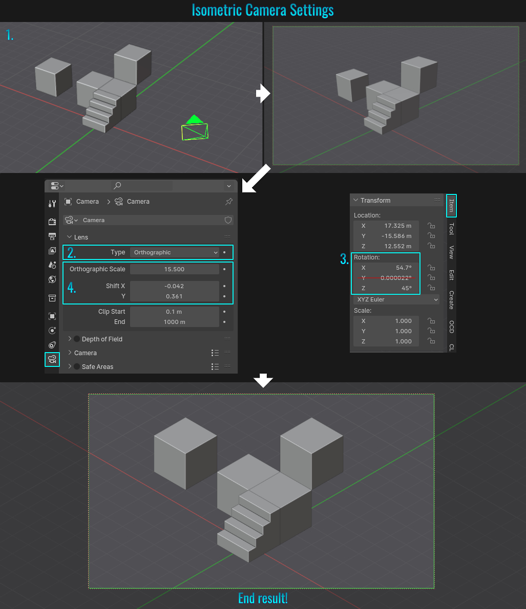
- Hook & Laplacian Deform Modifiers
While you can use a lattice deformer to deform a mesh (see tip Lattice Deform), this might not always be practical. In some cases, a combination of hook and laplacian deform modifiers can be used instead. This allows you to roughly pose a mesh using
a set of anchor vertices (which have Empty objects attached to them - this is where the hooks come in). The results here might not be very accurate, but will allow for general deformations! The steps are as follows:
- Start by selecting a vertex (or vertices) you wish to anchor and press Ctrl + H (this brings up the Hooks menu). Choose the first option in the list (Hook to New Object). Rinse and repeat this step for other strategic vertices in other areas of the mesh (in this example, a vertex along the cylinder top and bottom).
- While still in Edit mode (best to have no vertices selected), press Ctrl + H again and choose Select Hook > the first hook in the list. Repeat this step, each time selecting the next hook. All hooks must be selected one by one via this process! The result should be all hooked vertices being selected.
- Press Ctrl + G (to bring up the Vertex Groups popup) and click the Assign to New Group button. This in effect groups all hook-related vertices into a vertex group.
- Finally, in Object mode and with the mesh selected, add a LaplacianDeform modifier! From within that modifier, click the Anchor Weights field and choose the vertex group that was just created and then click on the Bind button!
Now when you select and move Empty objects, the mesh will deform! Feel free to play with the Strength and Falloff types from within the Hook-Emtpy modifiers if you want more fine tuned control!
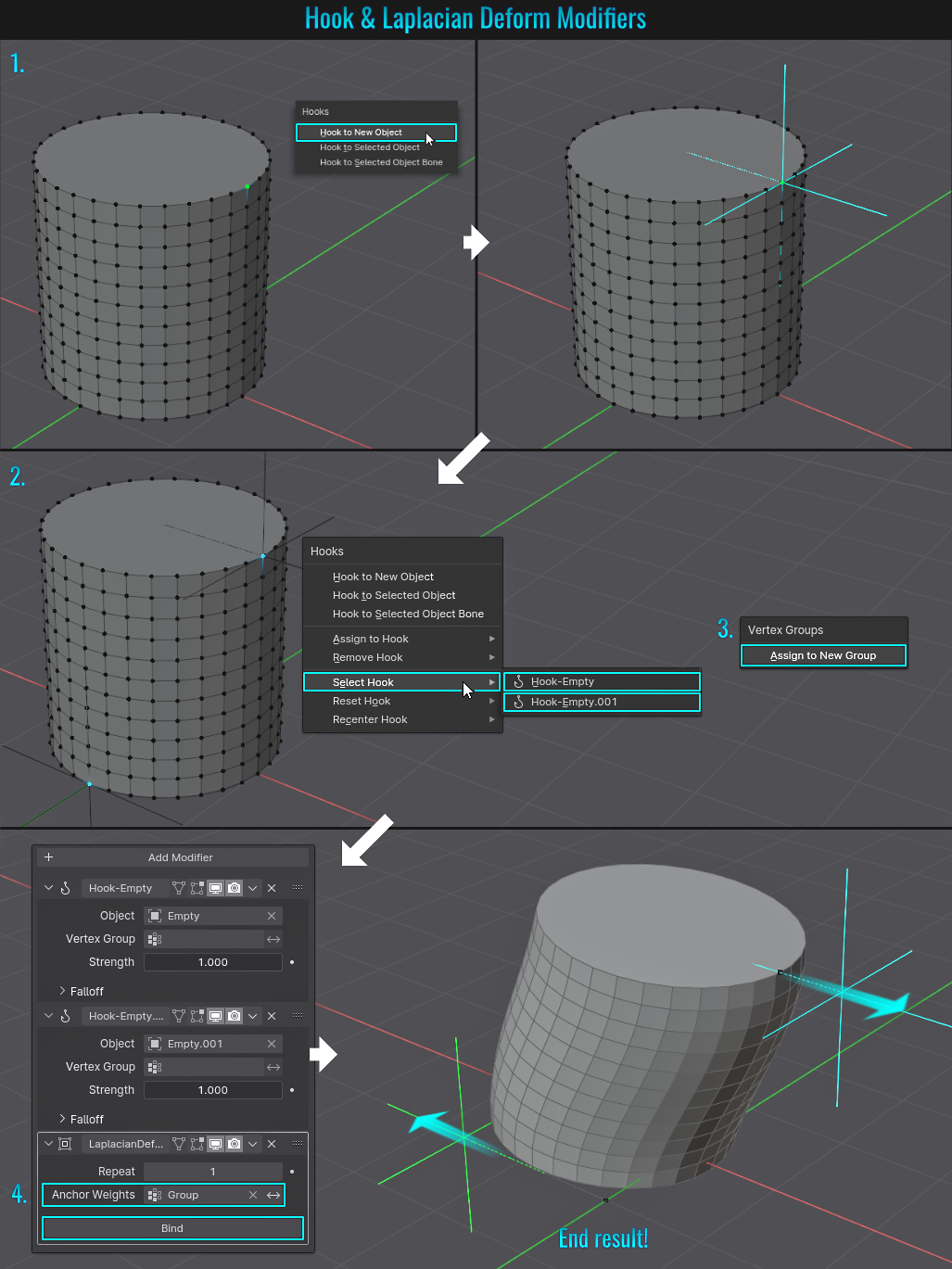
- Swap Two Node Input Connections
When it comes to swapping two input connections on a node, simply select the node and press Alt + S. It's important to note that in the event of three or more input connections involved, only the last two will be affected!
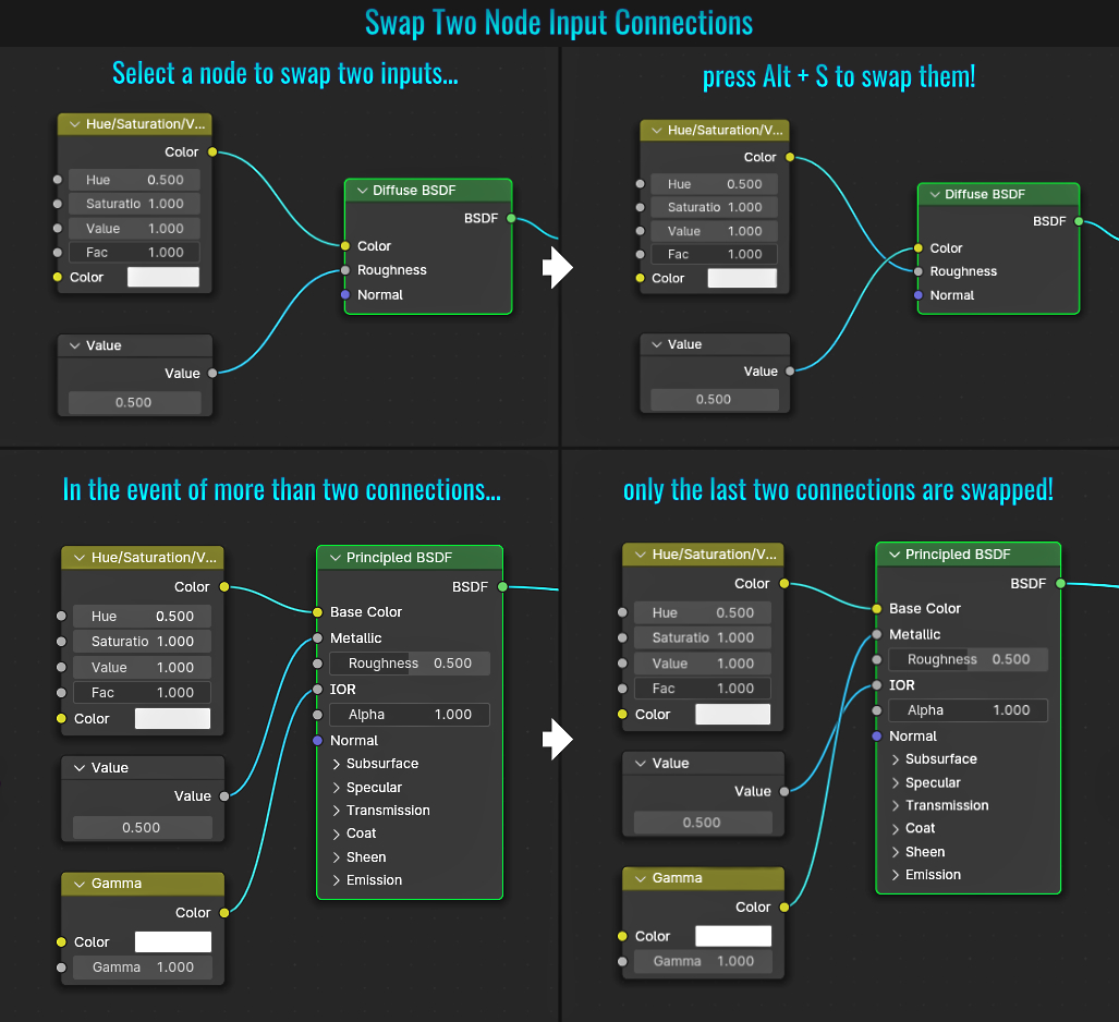
- Presets
With the rendering engine set to Cycles, ever notice that some tab panels contain some options that have what appear to be bullet list icons next to them? These are presets that enable you to rapidly change panel settings! Additionally, you can set the settings you wish and even save those out as new settings! Many presets from performance to camera settings and many more are available. Quite handy!
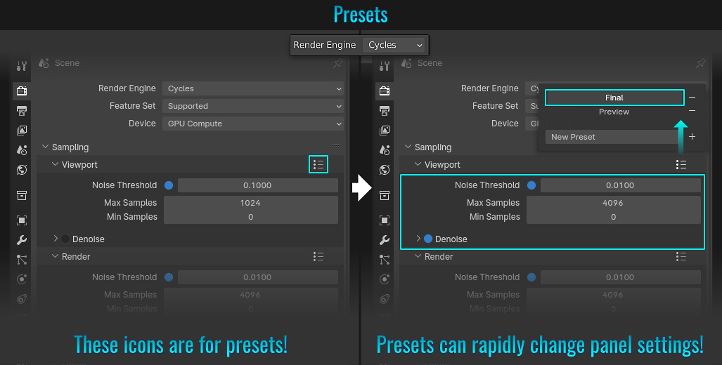
- Scaling Curve Points
Blender gives you the ability to scale points on a curve to give great control over various thickness! A curve in the scene with a Bevel Profile in the Curves Data Object Properties tab and a vertex (or vertices) along the curve selected in Edit mode, press Alt + S to scale them! For precision scaling (like tapering the ends to a fine crisp point), perform a scale and left click to end its operation. In the resulting viewport's lower left hand side Transform panel, set any of the corrosponding X,Y or Z Values numerically to zero! Otherwise, adjust to your liking!
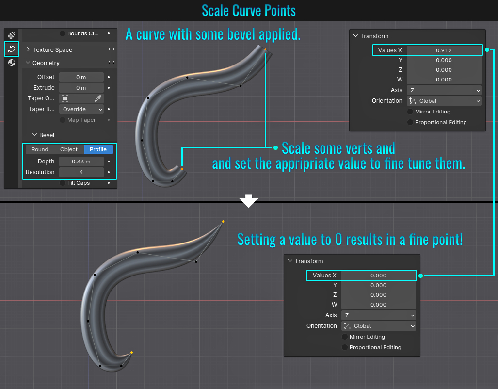
By scaling various points along various curves, many creative possibilities are open (especially when dealing with ornamental details)!
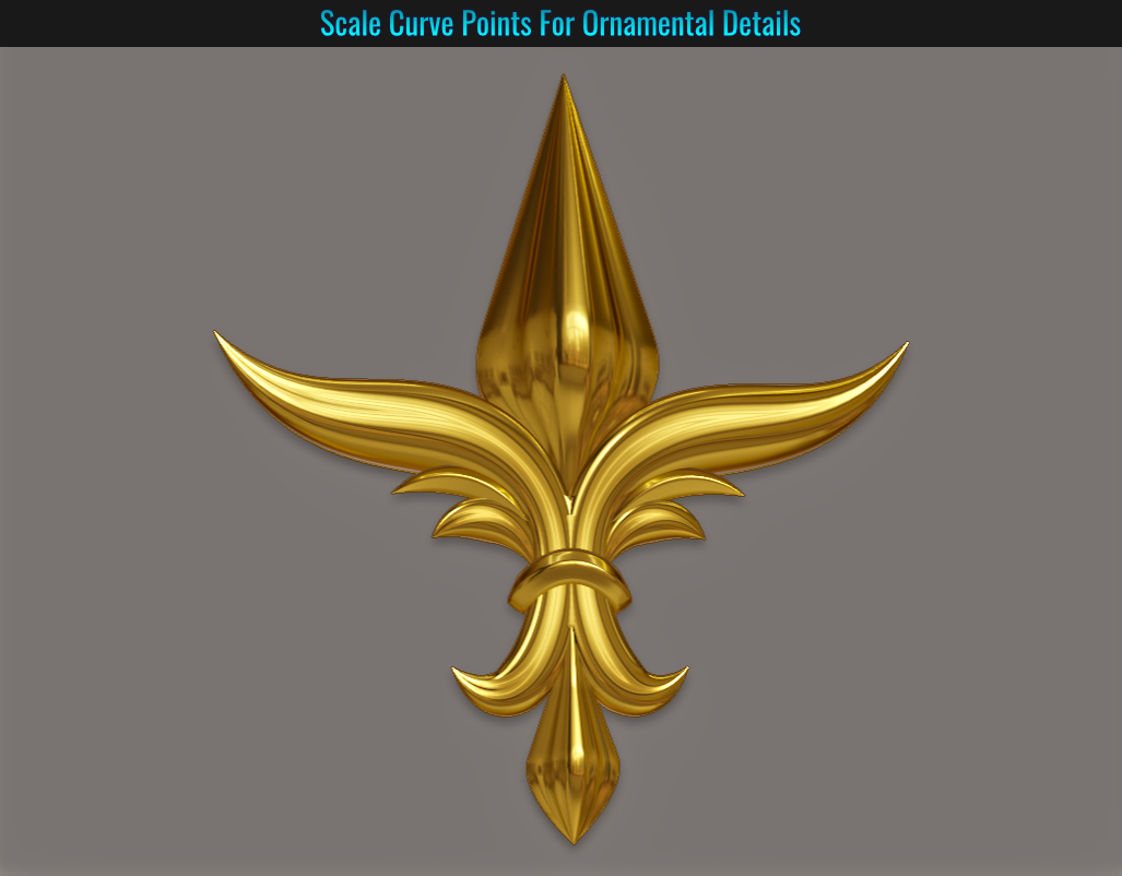
Sometimes you might have something far in view in your scene and you wish to zoom in on it. One way would be to select it and zoom in on the selection. But what if you don't want/need to select anything and just want to generally zoom in? The solution here is to simply press Shift + B and box marquee around the area you wish to zoom in on and voila! Instantly zoomed in!
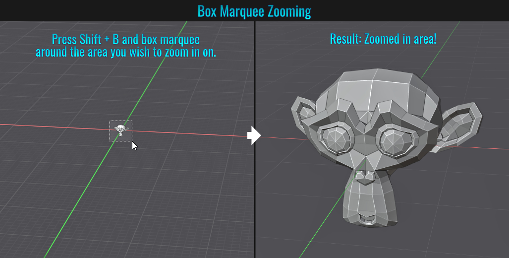
- Weld Edges Into Faces
Sometimes you might run into a situation where there is loose edge(s) sitting along face(s) in the same mesh (or this can be deliberately done for speeding up some quick edge prototyping) and you want to merge (weld) those edges into the faces directly! This is very easy to do. With all your
mesh faces selected, you can either:
- Go to Face > Weld Edges into Faces from the top viewport menu -or-
- Press Ctrl + F (to bring up the Face menu) and choose Weld Edges into Faces from there.
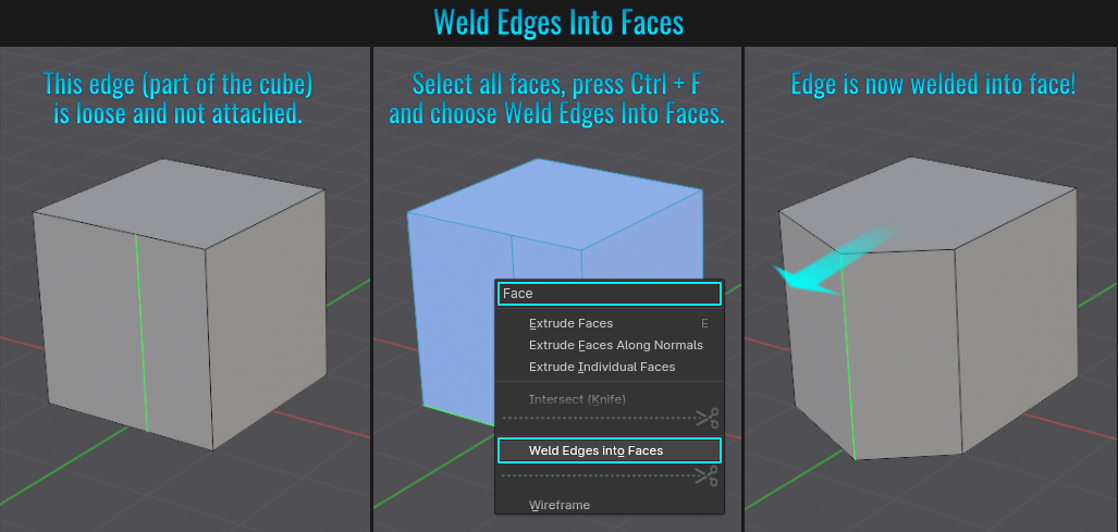
- Select Side Of Active
If you need to select one half of a mesh (or even just all vertices beyond a certain point), simply select a vertex on the mesh that you wish to use as a starting point (if it's a mirrored/symmetrical mesh, this would be a vertex along the center somewhere), and from within the viewport's top menu,
choose Select > Side of Active!
Blender will make use of the default settings within the Select Axis panel in the lower left hand side of the viewport. Here, you can change the settings for Axis Mode (global, local, view, etc...),
Axis Sign (positive or negative), Axis (X,Y or Z) and Threshold! Usually just adjusting a setting or two can fetch the results you are looking for and makes potentially combersome selections a quick and easy task!
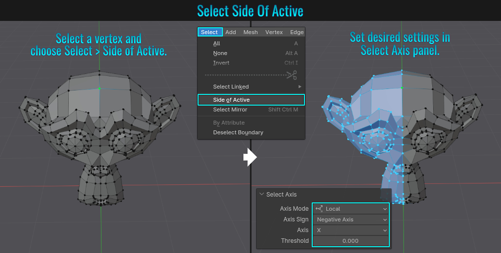
- Scale, Rotate & Move Nodes
This might come as a surprise (but in hind sight, shouldn't given the nature of how Blender works). Did you know that you can scale, rotate and move nodes using the typical S, R and G keys respectively? This only affects node locations! While scaling, you can also restrict this operation to an axis by pressing X, Y or MMB and dragging horizontally or vertically! Who knew?
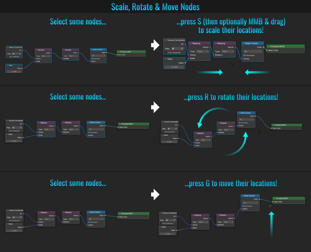
- Installing & Accessing HDR Images
One way to light your scene is by using HDRI files. You can download HDRI files over at Polyhaven.Once you have, here is a perhaps less known yet nifty way of installing and
accessing them!
- Ensure that the viewport shading mode set to Material Preview. Click on little down arrow in the Shading menu along the very top right hand corner of the viewport to open up the Viewport Shading dropdown panel. Here, you can click on the HRDI sphere previewer to open up the previews of stock HDR images. Clicking on any one of these will change the HDRI lighting accordingly! Notice that the amount of HDR images that ships with Blender isn't plentiful! No worries! We can install new ones that you have downloaded!
- To begin the installation process, simply start by clicking on the gear (options) icon.
- This will bring up the Blender Preferences popup with the Lights catergory preselected. Click on the Install button next to the HDRIs header.
- Navigate to the folder where you stored your downloaded HDRI files, select the ones you want and click on the Install Light button.
- Notice that once the installation process is completed, the HDRI panel is populated with preview thumbnails of all the current files.
- Returning to the Viewport Shading dropdown panel and clicking on the HRDI sphere previewer will showcase larger preview buttons of all the installed HDRI files. Clicking on one will switch the scene's HDRI and shade the geometry accordingly!
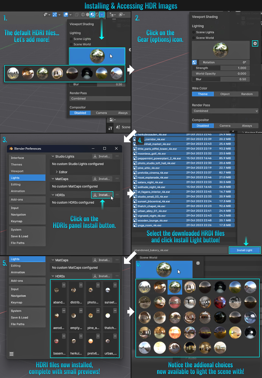
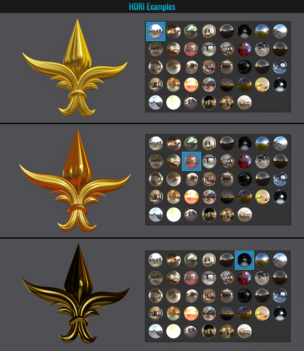
- Using Text Editor For Notes
There may come a time when you would like to take notes regarding a scene (perhaps for your self or reviewing someone else's work). Here's how you can add a Text Editor to your scene!
- Start by hovering your mouse cursor over the very top left hand corner of a window (say the Properties window). The cursor should change to a white plus symbol and simply click and drag in the direction you want to create the new window.
- Within this newly created window, click on the Editor Type button and from the resulting popup, choose Text Editor.
- Voila! That window is now a designated text editor where you can add any notes!
When you save the scene, the layout along with the text notes comes along for the ride! See tip Don't Load Someone's Layout In A Blender File and do the inverse of that info if the layout does not
load with the text editor in the file you just saved - as you must ensure that Load UI is enabled in the preferences for this to work!
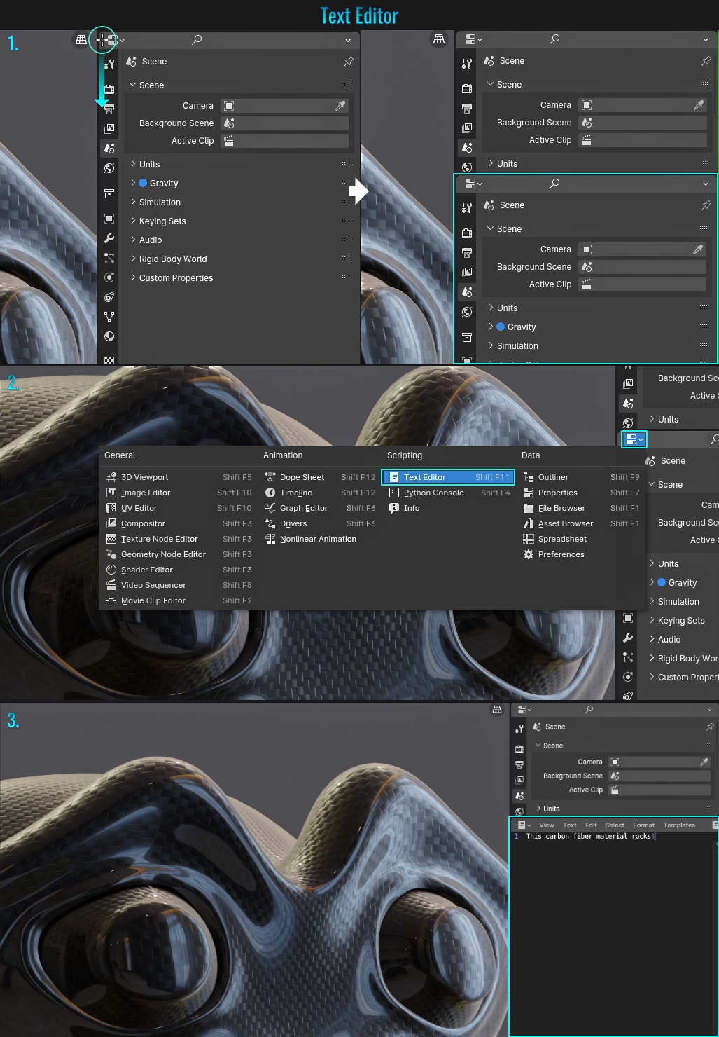
- Image Editor Drag & Drop Colour Swatch
It is possible to drag and drop images into the Image Editor for easy reference. Let's examine how to make use of a downloaded colour swatch for quick and easy colour sampling!
- Start by hovering your mouse cursor over the very top left hand corner of a window (say the Properties window). The cursor should change to a white plus symbol and simply click and drag in the direction you want to create the new window.
- Within this newly created window, click on the Editor Type button and from the resulting popup, choose Image Editor.
- Open up your file browser, locate the downloaded colour swatch image file (you can grab swatches from many online sources such as coolors.co for instance) and click drag it into the image viewer.
- Finally, click on a colour field (say the Base Color from within your material for instance) which will bring up the colour wheel popup, then click on the Eyedropper button and sample a colour from the colour swatch image within the Image Editor!
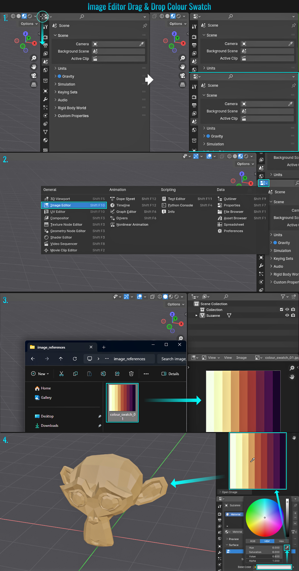
- Snap One Object To Surface Of Another
From time to time, you'll need to snap one object to the surface of another. This can be done via the tip Drag & Drop From Outliner, but this method will rely on specific snap settings and doing everything from within the viewport directly. Either way
will work!
Start by ensuring that the origin point of the source mesh is properly positioned (this is important as this will determing how much this mesh sits onto the target one). Next, either hold Ctrl + Shift + Tab or click on the
dropdown arrow next to the Snap icon along the top viewport's icons to bring up the Conform Object panel. Here, you only need to set the Snap With setting to Center (as this will make use of the origin as mentioned earlier), the
Snap To to Face, enable the Align Rotation to Target and ensure that both Move and Rotate are enabled from the Affect section.
Finally, with your source mesh selected, press G then hold down
Ctrl and left-click drag it into the desired position on the target mesh!
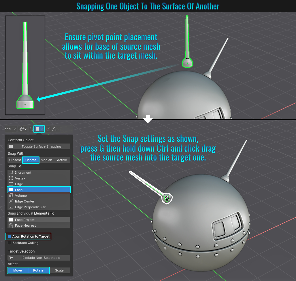
- Fill All Mesh Holes
Sometimes you might be dealing with geometry that has unintentional holes in it (could be an imported mesh or perhaps you accidently deleted some mistakenly selected faces). Filling those holes is pretty quick and easy!
- Simply go into Edit Mode (either in vertex or edge select mode - face select won't work), then from within the viewport's top menu, choose Select > Select All by Trait > Non Manifold. This should result in all hole vertices or edges being selected.
- Finally, simply press F to fill them in!
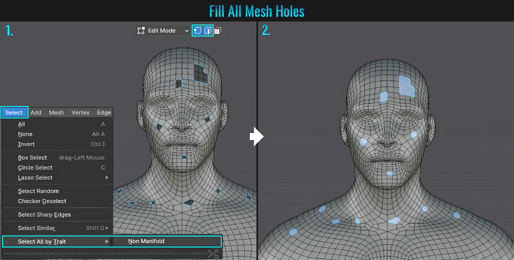
- Trim Corners
There are probably a myriad of ways to make meshes conform to corners. Here, we'll focus on two methods, one making a 90° corner and the other making a corner containing an unknown angle. This first screenshot contains a sample scene which breaks down the components for easy reference. The crown molding trim model labeled A will be used for making the normal corner and the other model labeled B will be used for some arbitrary angle corner.
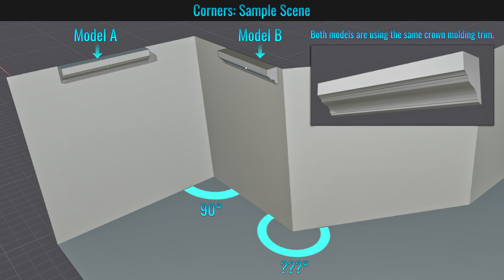
Method 1: 90° Corner Using Shear Tool
This method (using Model A) involves shearing a selection of an end face! Once the shearing is done, it's simply a matter of extruding in the perpendicular axis to finalize the 90° corner! To be clear, method 2 could also be used to acheive 90° angles (or any angle
for that matter). This first method merely shows how this could be done using the shear tool and extrusions!
- Position the molding (in this case, Model A) flush against the wall and aligned with where the wall meets the ceiling and the corner (this can be done afterwards of course... in this case, the mesh is not snapped to the corner to help better visualize what's happening). Next, select the model's end face (or if there are no faces, you can select the end edges/vertices).If the left hand icon menu in the viewport is not visible, press T to bring it up and select the Shear Tool.Start shearing the selection in the appropriate axis you need to angle along, then in the Shear properties panel in the lower left hand corner of the viewport, set the Offset value to -1 (or 1, depending on the direction of the corner in question!)
- Finally, with the sheared selection still selected, simply press E to extrude, followed by the axis key you wish to extrude the selection along (in this example, X). Voila! A 90° corner! Scale the selection flat in the appropriate axis and position the mesh directly into the wall's corner if need be!
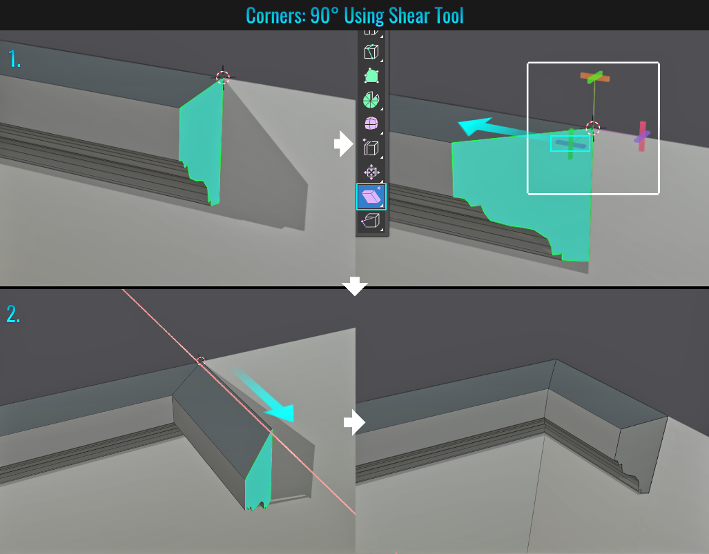
Method 2: Unknown Corner Angle Using Mirror Modifier
This method (using model B) involves the strategic placement of the mesh's origin point and making use of the mirror modifier along with an Empty Object to create an unknown angled corner (but as mentioned earlier, this method can be used for any
corner technically)!
- While this setup is rather optional, it just makes things easier as we go. Start by going in to Edit Mode and selecting the back upper edge of the crown molding Model B, then press Ctrl + Alt + X (to bring up the Origin Menu - you'll first need to ensure that the 3D Viewport Pie Menus add-on is enabled. It ships with Blender) and choose Origin to Selected. This will place the pivot point of the mesh directly on the back edge's center! Let's then snap the mesh to the vertex at the corner on the wall so that once the mirror modifier is added, we can "pivot" this mirror on the mesh's center (which conincides with the wall's corner). So press Ctrl + Shift + Tab to bring up the Conform Object snap menu and choose Vertex for the Snap To setting, and set the Snap With value to Center. Then hold Ctrl and snap the mesh to the wall corner.
- Add an Empty Object (Ctrl + A > Empty > Plain Axis) and snap this to the same wall corner vertex much like we did with Model B.Now with model B selected, go to the Modifier tab and add a Mirror modifier. Within this modifier, set the Mirror Object dropdown to point to the Empty Object. Then set the values for both Axis and Bisect to Y (this might depend on your cornering orientation and you might need to set those to X or Z... experiment and see which ones works for you).
- Finally, rotate the Empty Object in the Z axis (press R then Z then click drag - once the rotation is near its final position, hold Shift to slowly fine tune this) until the mirrored model aligns with the side of the wall after the corner! Because of the bisect option, there is no need for messy booleans/mesh cleanups afterwards!
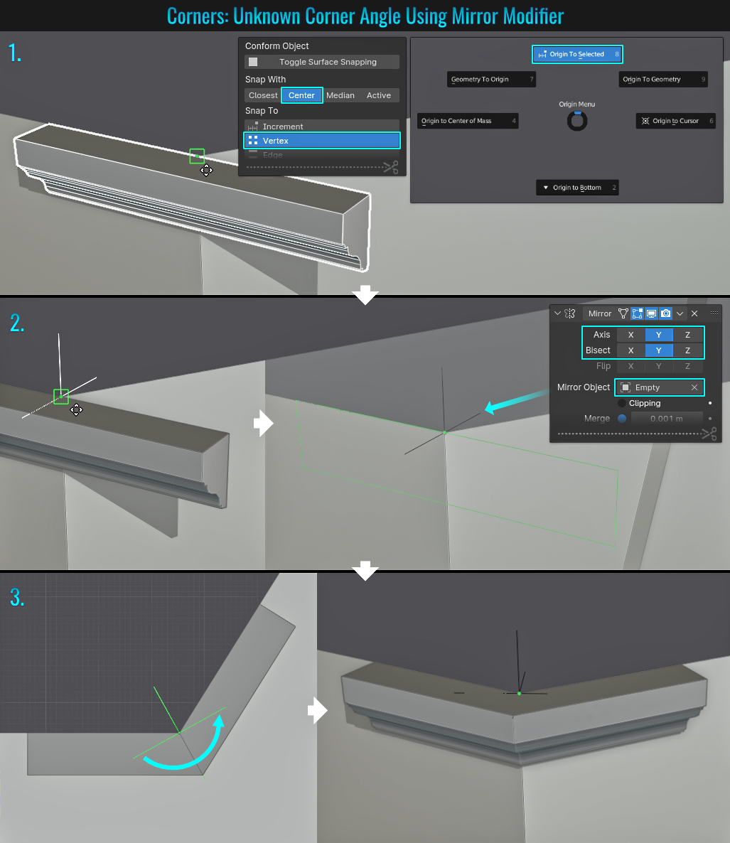
- Conforming One Object To Another
There are a couple of ways to conform one object to another. We'll start with a native solution, right in Blender without any need for add-ons! More methods to come later.
Lattice & Shrinkwrap Modifier
This method makes use of a lattice along with a shrinkwrap modifier! Let's examine how to make the initial setups to accomplish a 3d triangle symbol comforming to a capsule-shaped container. The symbol needs to have enough vertices to properly deform, so a
Subdivision modifer is used! For a refresher involving lattices, see the tip Lattice Deform for more details. Here is the example scene for this demonstration.
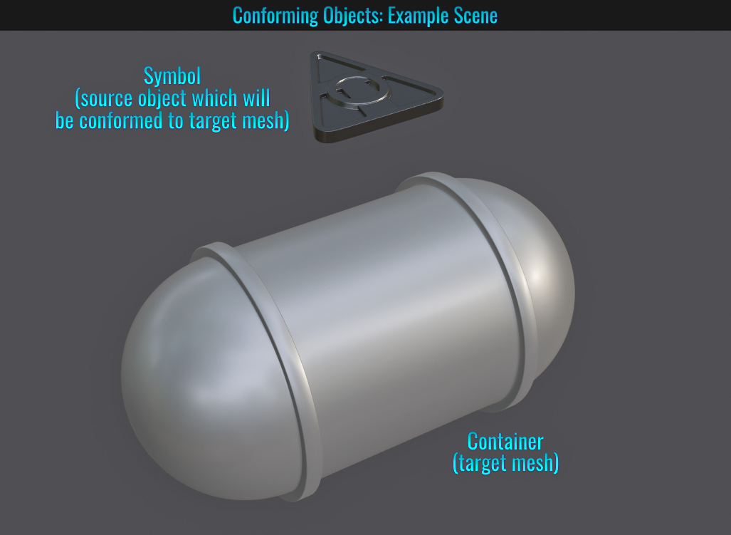
- First we need to setup our snapping settings! Press Ctrl + Shift + Tab (to bring up the Comform Object panel) and select Face Project from the Snap Individual Elements To section and enable the Align Rotation To Target option. Next, Press Ctrl + A and add a Lattice object. From within the Object Data Properties, set the Lattice's U and V Resolution values to a comfortable amount and ensure that the W value is set to 1! Now position and scale (in Object Mode only) this lattice so that it overlaps the object you wish to be conformed (in this case, the symbol) from the top view and sits near the bottom from the side view.
- Next, select the source mesh (in this case, symbol) then hold Shift and select the lattice. Press Ctrl + P (to bring up the Set Parent To popup) and choose Lattice Deform. Now select the lattice, and from the Modifier tab, add a Shrinkwrap modifier. Within the Shrinkwrap modifier, from the Target field, either choose the target (the mesh which the symbol will conform to - which in this case is the container) from its dropdown list, or use the eye dropper and manuallly click on the target itself.
- Once the lattice object is snapped and conformed to the target mesh, it might look visually broken at first. Simply press G, then hold Ctrl and move the lattice around to force a corrected conformation! Due to the snap settings we first established, the lattice will now glide along the target mesh's surface. You can fine tune the Offset value within the Shrinkwrap modifier to adjust the symbol's height from the surface!
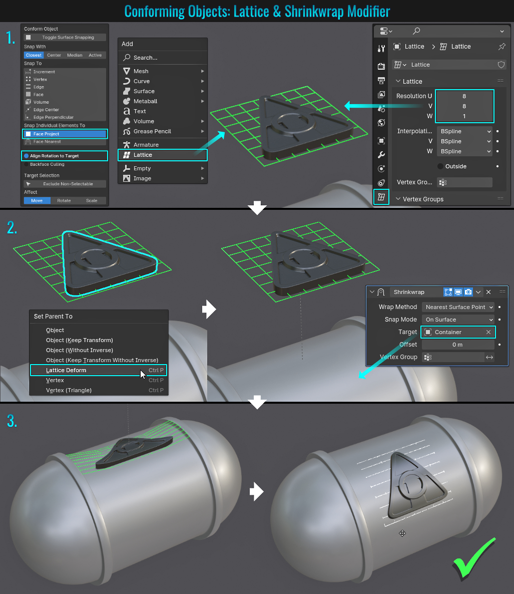
- Rounding Edge Loop Corners
The included (but not enabled by default) add-on called LoopTools offers some seriously robust modelling features. So if you don't have this enabled, simply go to Edit > Preferences and from within the Add-ons panels, search for the term loop and enable it by clicking on the LoopTools entry. Now that you're setup, let's look at how to easily select some hard corner edges on say a grid of geometry and round them out (to say potentially extrude inwards afterwards for example)!
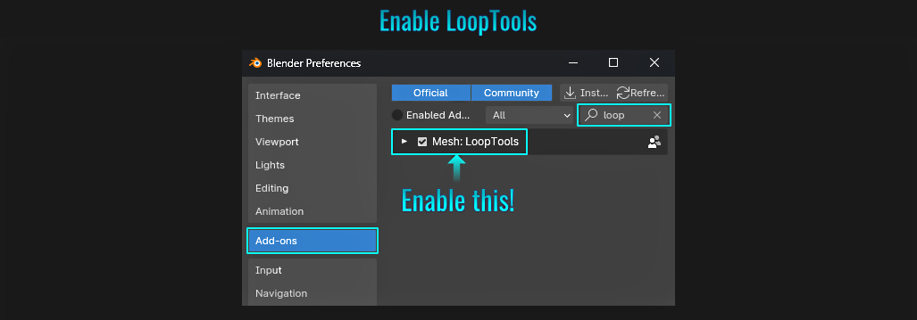
- First select some edges on the grid that form a "corner" that you wish to round out. The thing to note here is that you only need to select a few edges for form a corner, as more segments selected will not result in a larger radius once all is said and done.Right-click to bring up the contextual menu and select LoopTools > Relax (alternatively, you can press N to bring up the right-hand viewport side bar and choose this option from within the Edit tab).
- In the resulting Relax properties popup in the lower left hand corner, set the Interpolation value to Linear (otherwise, if left to the default Cubic setting, the rounded edge results bulge outwards beyond the surrounding straight edges selected). Finally, set the Iterations value to between 1 and 3 (setting it higher might cause the rounded corner to be too agressive, causing visual issues, depending on the spacing between edges)!
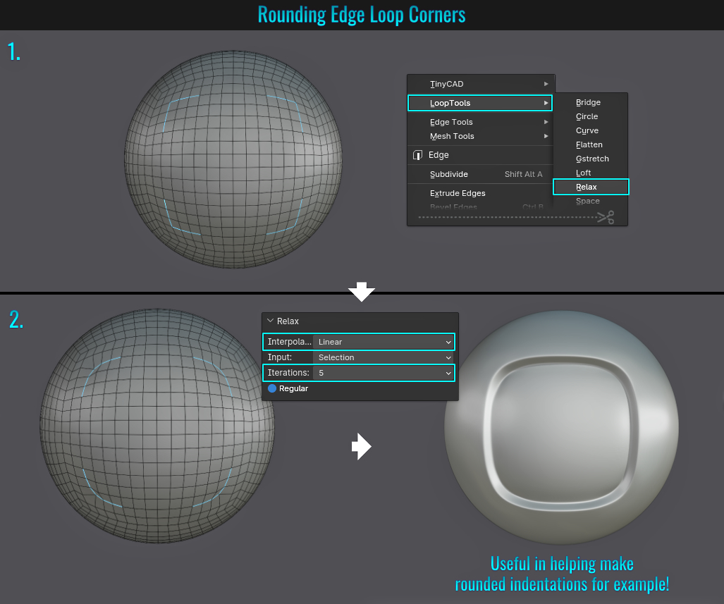
- Hanging A Flag
Making a hanging flag in Blender is quite quick and simple, due to its easy to use cloth physics system. Let's have a look at how simple it is to setup!
- For starters, ensure that the flag mesh in question has enough length and width segments to be able to properly deform (using Ctrl + R in Edit mode to establish vertical and horizontal cuts - For best results, try to make the segments as square as possible)! Rotate the flag (if need be) and position it correctly relative to whatever the flag is attached to (in this case, an angled flag pole). In Edit mode, select the two top flag mesh corner vertices and press Ctrl + G (to bring up the Vertex Groups popup) and click the Assign to New Group button. This will automatically create a group with those corner vertices assigned to it. If you wish to rename the group, simply click on the Data Object Properties tab and from within the Vertex Groups panel, simply double click the defaulted Group name and rename it to something more appropriately descriptive (in this case, flag corners).
- Now head over to the Physics tab and click on the cloth button. This will open up a Cloth panel. Here simply scroll down to near the bottom to locate and open up the Shape sub panel. Here, you will find a Pin Group text field at the very top. Simply click in this field and select the vertex group you just created.
- You might notice the flag just disappear! If this is the case, don't worry, the cloth physics simulation uses animation for its calculations. So from within the Layout workspace, press the Jump to Endpoint left pointing arrow button to select the first frame. The flag should reappear where it was initially placed. Now simply play the animation and watch the cloth system do it's thing and pause the animation where you feel you have a great result! Voila! A quick and easy hanging flag! If you need the flag mesh to retain this state in the animation (perhaps you wish to export it for the purpose of bringing it into a game engine), simply apply the flag mesh's cloth modifier!
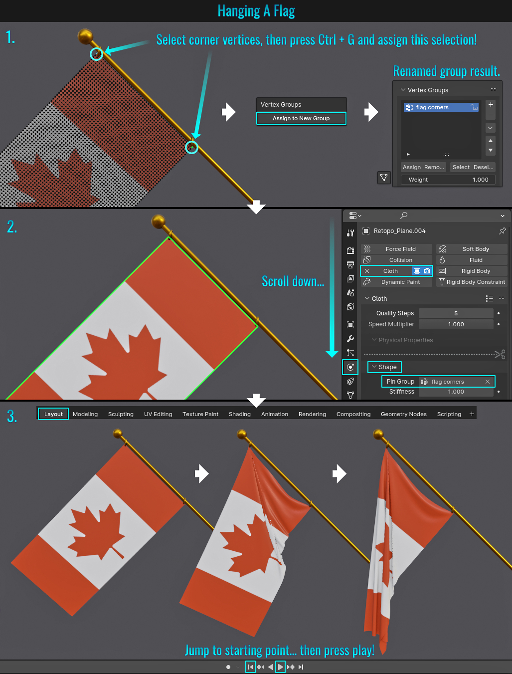
- LoopTools Gstretch Using Annotations
LoopTools is an included add-on in Blender that offers a wide array of useful functionalities! If this isn't already enabled, see the first screenshot in the tip Rounding Edge Loop Corners to see how to enable it!There are a few ways on conforming vertices
along an edge loop to a curve. This method makes use of LoopTool's Gstretch function!
Creating And Conforming To The Curve
- Starting with a mesh containing enough length segments, select the vertices of an edge loop that you wish to curve. Next, press N to bring up the right-hand viewport tabs and select the Edit tab. From within the LoopTools panel, click on the arrow next to the Gstretch subpanel to open up its options. From within the Use guides dropdown, set this value to Annotation.
- Next, click on the Annotate tool from the left-hand side viewport toolbar (press T from within the viewport if this is not visible) and proceed to draw an annotated curve directly above the selected row of vertices.
- Finally, click on the Gstretch button itself within the LoopTools panel and the selected vertices will follow the curvature of the annotated line you just drew!
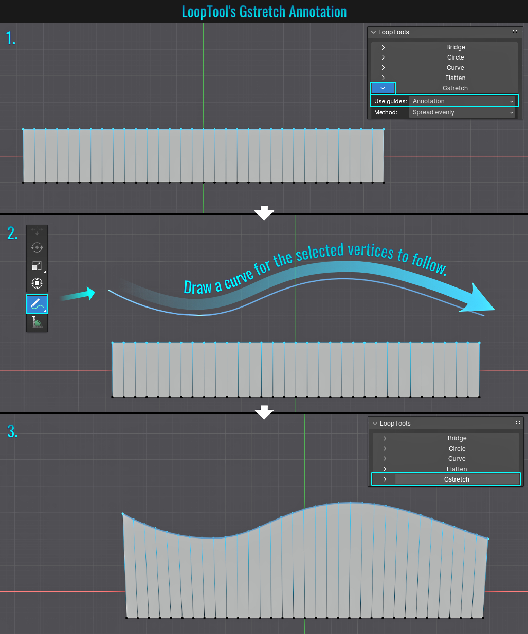
Removing The Annotation Strokes
To Cancel this operation (the vertices must still be selected), you can simply open up the Gstretch properties panel in the lower left-hand side of the viewport (or from within the viewport
LoopTools > Gstretch side panel) and simply click on the Delete annotation stroke!
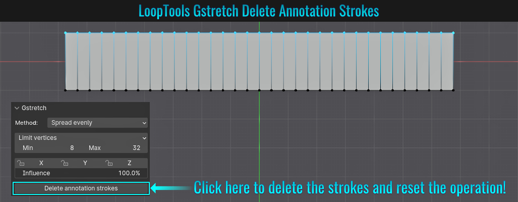
If you are happy with the results and want to clear the stroke, start by simply pressing Alt + A (to deselect all the vertices) and either:
• click the Delete annotation stroke button from within the Gstretch viewport side panel. -or-
• simply go
into the View tab from the viewport side bar and from within the Annotations panel, click on the minus button (or alternatively, you can right-click on this button and assign it to the Favorites menu for faster access)!
- Pick Shortest Path Fill Region
When it comes to selections, clicking on one element (point a) and while holding down Ctrl, clicking on another element (point b), Blender will select everything inbetween using the shortest path. As a result, there is a Pick Shortest Path panel that
pops up in the lower left hand side of the viewport.
Enabling the option Fill Region will do exactly that! It will select fill the faces that fall between both points! But instead of having to manually enable this, the quicker way is to left click on point a, then simply hold
down Ctrl + Shift while left-clicking on point b! This method is faster/more efficient than otherwise manually making the equivalent selection through other selection means!
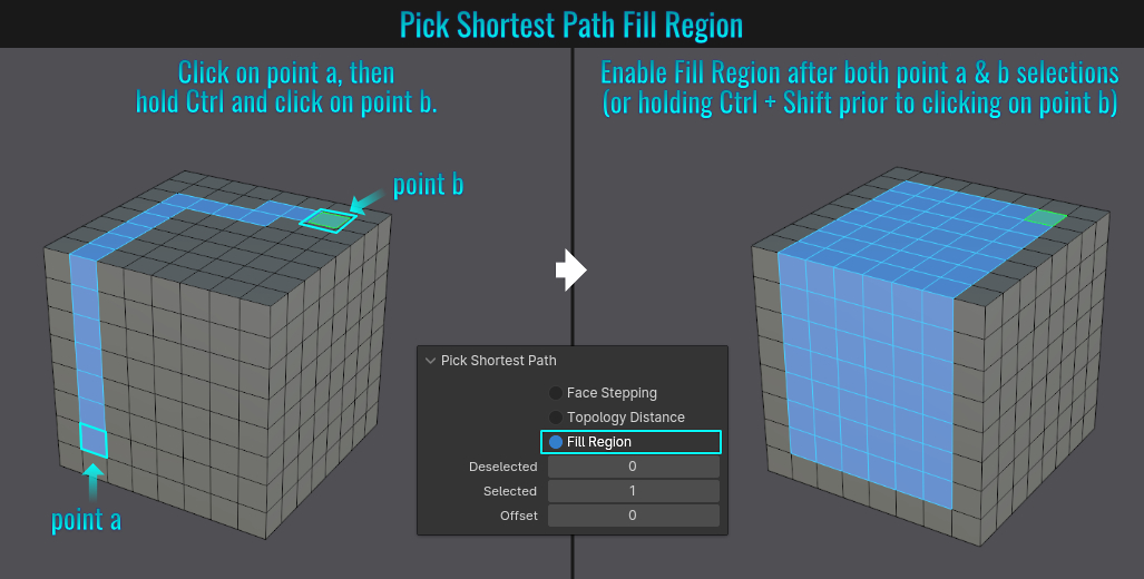
- Rendering Micro Bevels
While you can certainly model micro bevels into your geometry, it is possible to have these bevels rendered on simple geo as well (assuming the goal is only final rendered outputs as this doesn't effect the actual geometry itself). We'll examine how to render micro bevels in Cycles. Let's look at the starting mesh as our example. Notice that there are no micro bevels in the geometry.

Rendering Micro Bevels In Cycles
- The first step is to head over to the Render Properties tab and set the rendering engine to Cycles. Next, within the top right hand side of the 3d viewport, set the viewport shading method to Rendered. A sun light source has been added to accentuate the bevels to come!
- With the mesh selected and from within the Material Properties tab, click the New button to add a new material to the mesh. Then select the Shading workspace along the top of the viewport. We will keep the basic Principaled BSDF node which is plugged into the Material Output node (feel free to tweak its colour, metallic and roughness settings to get something a bit more presentable). Next, left-click and drag from the Normal input of the prinicipaled BSDF node and once the mouse button is let go, look for and add a Bevel node.
- Finally, you can play with the Radius value to adjust the rendered bevel results! Keep to using lower values (via holding Shift while adjusting the value slider), as larger ones will look unrealistic and less pleasing!

- Chains Following A Curve
Making chains following a curve is quite simple, involving just a few simple steps!
- To start with modelling the chain link itself, feel free to visit the tip Extrude To Quickly Create Forms on how to make a chain link (experiment with the torus' segments and Major and Minor Radius values to establish the visual style you are looking for). Once you have your chain link, press Ctrl + A (to bring up the Add menu) and add a curves > path (or perhaps a bezier curve). This will be the curve we will use for the chains to follow along.In Edit Mode, move the curve's points to create the curvature you want the chain links to follow.
- Next, select the chain link mesh and from the Modifier Properties tab, add an Array modifier. Within the Array modifier properties, set the Fit Type to Curve and choose your curve for the Curve value. At this point, a linear array of chain links will appear to fit the length of the curve (but not yet follow it).
- Next, add a Curve modifier to the chain link mesh and from within the Curve properties panel, choose your curve for the Curve Object value. This chain link array will now actually conform to the curve itself!
- Go into Edit mode (at this point, you'll notice that the array no longer follows the curve - it's a linear array again)! This is normal. Once we go into back in Object Mode, this will be restored! Select all the faces fo the chain link, press Shift + D to duplicate it, then press G, then X and slide this duplicated link until the inside of its ring just touches the inside of the first link's ring. Now press R, X, type 90 and hit Enter to rotate this second chain link onto its side by 90°. It's now starting to resemble a proper chain... almost...
- Finally, back in Object Mode, go into the Array modifier and adjust the Relative Offset's Factor X value (holding Shift while click-dragging within the slider allows slower, fine tuned value adjustments) until the two sets of chain links align properly with the rest of the array! Done!

The beauty of this method is that if you adjust the curve in any way, the chain links will auto adjust to fit the curve!

- Value To String To Curve
Geometry nodes offers the ability to create strings that are then converted to curves! In the following example, we'll use a number as the string and see the end result dynamically generated within the viewport.
Value To String To Curve Node Setup
- Start by adding a cube. Head over to the Geometry Nodes workspace along the top of the viewport, and with the cube selected, click on the New button within the geometry node editor. By default, this will create two nodes (Group Input and Group Output) linked together. Hold Ctrl and right-click drag across the line linking those nodes to detach them (as we won't need to use the Group Input node for this). The cube will disappear from the 3d viewport. Don't panic! This is normal.
- Next, press Shift + A (to bring up the Add menu), find and add the following nodes;Value, Value to String, String to Curves and Fill Curve! Now it's time to connect them! Connect the Value node's Value output to the Value input of the Value to String node, which in turn connect its String ouput to the String input of the String to Curves node. Plug String to Curves' Curve Instances output to the Curve input of the Fill Curve node. Finally, connect Fill Curve's Mesh output to the Geometry input of the Group Output node.
- To change the value, simply play with the number in the Value node's text field. If you want additional decimals, change the Value to String's Decimal count to the amount you need!

Setting Random String To Curve Values
If you wish to have random values, simply disconnect the initial Value node and instead add an Integer node (connect its output to an added Random Value node's ID input) which in turn connects to Value input of the
Value to String node. The rest of the graph as left as is! From there, all that is really needed is to play with the Random Value node's Min, Max and Seed values to generate random numbers!

Animating String To Curve Values
Things like this offers plenty of dynamic, animatable string opportunities (especially in the field of motion graphics for example)! As a quick final example, restructure the graph such that an added Scene Time node is plugged into the Value input of the
Value to String node (you can choose to use either Seconds or Frame outputs from the Scene Time node). From there, go to the Layout workspace and hit the Play animation button along the bottom of the 3d viewport and watch the value to
string box object animate!

- Hanging Cables/Wires
Creating hanging cables/wires in Blender is not difficult. There are external add-ons out there that can accomplish these kind of things, but for now, the focus will be on plain vanilla Blender functionality. Let's look at one way on how we can acheive these kind of results!
Catenary Curve (Part 1)
The term catenary is a mathematical desciption of a curvature regarding cables/wires/chainlinks and the like (herein referred to simply as cables for brevity sake) that are anchored at both ends and naturally hangs under its own weight with uniform gravity applied.
In blender, there is such a function. Here's how it works: The idea here is to have two end piece objects that the cables will be suspended from (these represent the anchored points). It's important to understand that this catenary function uses the
origin points as the start/end points of the curve it will generate! These can be origins of meshes (such as walls or in this example, electrical towers) to things like a pair of empty objects or even lights (though that last one would be really weird!) There are plenty of
possible options! Here is an electrical tower that will be used for this example:

- First, go into Edit > Preferences and from within the Add-ons panel, search for extra and enable the Add Curve: Extra Objects add-on (as the catenary function relies on this).Next, create the tower (or whatever mesh you intend to use as the anchor) and feel free to position its origin points via the tip Origin Point Placement (making use of either a specific selection or manually placing it). Place another copy of this mesh facing the first one in the desired location (these will represent both anchoring points for the catenary curve). Select both meshes, then press Shift + A (to bring up the Add menu) and choose Curve > Knots > Catenary. This will auto generate a catenary curve between the two towers!
- Within the resulting Catenary properites panel that shows up in the lower left-hand side of the viewport, here are some tweaks to change the curve's appearance:
2a Bevel Radius will add a thickness to the curve.
2b a (not the most creative variable name) will adjust the curve's amplitude.
2c Bevel Resolution will add profile segments to affect how round the curve becomes.
2d Extrude will create flatter/wider (capsule profile looking) curves.
2e Randomise will randomise spline control points resulting in "waves" within the curve.
2f Tilt will apply a tilting rotation to the curve.

Catenary Curve (Part 2) - Cable Clusters
In this example, we'll use a catenary curve to create a cluster of cables. Different towers will be used as anchor meshes instead (for a larger surface area to accommodate the cluster). The recipe is largely similar to the example above, but diverges a bit in workflow and object requirements.
- First, press Ctrl + A (to bring up the Add menu) and choose Curve > Circle. Duplicate and rescale these additional curve circles (using Ctrl + D and Ctrl + S respectively) and position them close together (this will in essence become the profile of the hanging cable clutter!) Select all curve circle objects and press Ctrl + J to join them together. As always, place the towers (or whatever you choose to use) facing each other at the desired distance apart, with their origin points strategically placed.
- Next, with said towers selected, press Shift + A and like in the example above, choose Curve > Knots > Catenary. Simply adjust the a value to decide the curve amplitude (but feel free to play with the Steps and/or other settings if you wish to make some additional tweaks).
- With this catenary curve still selected, go to the Curve Data Properties tab, locate and open the Bevel panel (found within the Geometry panel) and switch it's mode to Object. Finally, from within the Bevel Object dropdown menu, select the curve circle you just created. Voila! Instant cable cluster!

Here's the twist to all of this! Optionally, you can select one of the cluster curve end points, press O (to activate proportional editing), then press Ctrl + T and start moving the cursor in circles to start adding a twist (while scrolling the mouse wheel to expand the twisting influence)!

- Creating A Hexagonal / Pentagonal Sphere
While there is no default primitive to create such a sphere in Blender, creating one is surprisingly simple! The method below will not produce a sphere only comprising of hexagons, but also include twelve pentagonal faces as well.
- Press Shift + A (to bring up the Add menu) and choose Ico Sphere. From within the Add Ico Sphere properties panel in the lower left-hand side of the viewport, increase the Subdivisions count to 4!
- From within the Modifiers tab, add a Subdivision Surface modifier (leaving the default settings alone) and apply it (either by clicking on the down arrow next to the camera icon at the top of the modifier and choosing Apply or simply hovering your mouse cursor over the modifier and pressing Ctrl + A).
- Next, go into Edit Mode and select a central vertex in one of the hexagonal shapes, press Shift + G (to bring up the Select Similar menu) and choose Amount of Connected Edges. All vertices that have the same amount of connected edges become selected. Now just press Ctrl + X to dissolve that selection!
- Now, only pentagonal shapes will contain central vertices! Select one of those central vertices and once again repeat the Select Similar > Amount of Connected and dissolve those as well!
- Finally, select any of the center edge vertices and once again go into the Select Similar menu, but this time choose Amount of Adjacent Faces. All central edge vertices will become selected. You know what you need to do! Yup, dissolve them too! What remains is a hexagonal / pentagonal sphere!

- Mirror Selection On Symmetrical Mesh
When it comes to modifying one half of a symmetrical mesh, you would simply mirror this change to the other half. But did you know you can simply make a selection, then press Shift + Ctrl + M (which brings up the Select Mirror properties panel in the lower
left-hand side of the viewport) and effectively mirror it?
Here, you can choose the desired axis. But by default, the selection will mirror (read:"transfer") to the chosen axis side of the mesh. Enable the option Extend to once again bring back the original selection as well!

- Weighted Normal Face Influence
The purpose of the weighted normal modifier is to change the custom normals on a mesh, through selected elements, giving you more visual control! In the following (admittedly non-impressive, over simplistic example), we'll exmine how to change face normals in particular to allow us to
determine which ones remain nice and sharp while others blend together!
Here is the base model (showcasing the wireframe as well as face "blemishes" due to how the normals are affected by invisible face triangulations) using the ceramic_lightbulb matcap material:

- With the mesh selected, right-click and choose shade smooth by angle (setting the angle to 180 degrees). Turn off Keep Sharp Edges if you want total control over face sharpness!
- Next, from within the Modifier tab, add a Weighted Normal modifier (from Blender 4.0+, this can be found within the Edit dropdown once you click on the Add Modifier button).
- Within this modifier's panel, enable the Face Influence option.
- Finally, select the desired face(s) (especially coplanar ones that exhibit hidden triangulation shading issues) and press Alt + N (to bring up the Normals) menu and choose Set Face Strength > Strong!

- Making A Wave Using A Custom Bevel Profile
There are many ways to create a wave in geometry, but this method focuses on using a custom bevel profile to achieve this!
- Press Alt + A (to bring up the Add menu) and choose plane. Now scale the plane along an axis to the desired length and then press Ctrl + A (to bring up the Apply Transform menu) and choose Scale.
- Next, in any of the selection modes (vertex, edge or face), press Ctrl + R (to add a loop cut) and insert a central edge (by simply right-clicking to insert it in the center). This edge needs to be raised up (pressing G, then Z and moving it upwards) for the bevel to work!
- With this raised edge still selected, press Ctrl + B to bevel it (while the tool is active, scroll the mouse wheel to insert the desired bevel segments and move the mouse left/right to spread the bevel out - if the bevel covers the entire length of the plane, this will leave duplicate vertices on the plane's corners - so you'll need to merge them by distance at some point afterwards).
- Finally, within the bevel properties panel on the lower left hand side, switch the Profile Type to Custom and left click to insert control points and move them within the profile grid. In turn, the plane will shift heights at the corrosponding edges to mimic what was done in the profile!

- Offset Edge Extrusions
Sometimes you may find yourself needing to extrude a set of edges inward (or outward) to form say the top of walls in a room for instance. This is known in Blender as offset extrusion! There is more than one way to do this, but thankfully, Blender offers a very simple solution! With a simple included add-on, let's look into how we can easily accomplish this!
- Start by going into Edit > Preferences and from within the Add-ons panel, search for edit and enable the Edit Mesh Tools add-on that is included with Blender. Then select the loop of edges you wish to extrude in an offset manner.
- Press Ctrl + E (to bring up the Edge menu) and choose Offset Edges > Extrude. You'll notice the all the selected edges now extrude (offset) outwards, instantly creating a boundary loop of faces that cleanly follow along the selected edge contours!
- Play around with the Width value to adjust the width (you can also choose Angle to adjust the angle of the extrusion)!

- Quick Edge Ring Selection
When needing to select all edge rings, simply select a single ring, then from within the top left hand side of the 3d viewport menu, choose Select > Select Loops > Edge Rings. Couldn't be easier!

- Preview Node Using Node Wrangler
Node Wrangler is an included add-on within Blender (but is not enabled by default). To enable this, simply go to Edit > Preferences, and from within the add-on side panel, search for node, find
Node Wrangler in the list and check the box! Next, from whatever scene you are working on, select a mesh with a material applied, and from within the Shading workspace, simply press Ctrl + Shift and left-click on whichever node you wish to preview
(meaning what does that particular node affect the mesh in question).
You'll notice that in doing so, the node you are previewing connects directly to the end Material Output Surface input! To get back the overall preview, simply once again Ctrl +
Shift and left-click on the node that normally connects directly to the Material Output node - in most cases but not always - this will in all likelihood be Principaled BSDF.

- Insert Unicode Character
Did you know Blender can make use of character unicodes? What is a character unicode you ask?
According to Google:
Unicode is an international character encoding standard that provides a unique number for every character across languages and
scripts, making almost all characters accessible across platforms, programs, and devices.
You can visit an example unicode chart site to see a list of different character unicodes! Notice that the character
unicode format is U+XXXX (where the Xs contain a series of numbers/letters relating to a specific character from the unicode list)! Example: U+0040 results in the ampersat symbol (@). As for making use of this in Blender, it's quite easy.
- Start by pressing Shift + A (to bring up the Add menu) and choose Text. A Text object (the word text) should appear in your scene!
- With this text object selected, simply go into Edit mode and erase the default text by pressing Backspace until all characters are gone and you are left with the text input cursor (caret). Right click (to bring up the Text menu) and choose Text > Insert Unicode. This will bring up the Insert Unicode Character popup with a simple text field.
- Simply enter the numbers/letters succeeding the initial U+ part of the character code you want and either hit Enter or press the Insert button! Voila! Unicode character inserted!

Note: Inserting character unicodes does NOT work in Blender 4.2.0! A bug was submitted, fixed and will work in 4.2.1. This does work in 4.1 however!
- Modelling A Knurled Knob
A knurled knob is really easy to model in Blender!
- Start by pressing Shift + A (to bring up the Add menu) and choose Mesh > Cylinder. You can scale this cylinder to your liking, but if you do, it's always a best practice to apply its transforms afterwards (Ctrl + A to bring up the Apply menu and choosing Scale - but not necessary in this case).
- Go into Edit mode, ensure you are in edge select mode, press Ctrl + R then hover the mouse over a vertical edge. Scroll the mouse wheel to insert the amount of edge loops (ideally you'll want to add enough loops such that the newly formed faces will be more or less square) and left click to finalize this!
- Finally, select all the faces on the cylinder (aside from the top and bottom caps - it's eaiser to go into say front view by pressing 1 on the numpad and then go into x-ray mode with Alt + X prior to selecting), right-click to bring up the contextual face menu and choose Poke Faces. In the resulting redo popup panel in the lower left hand side, adjust the Poke Offset value to instantly push or pull all the newly created face center vertices! Voila!

- Celtic Links
There's an easy way to add celtic links to a model. First, you'll need to ensure that the included Extra Curve Objects add-on is enabled from the add-on preferences. Next, select the mesh in question that you would like to convert to celtic links (in this case - a tea pot), then press Shift + A (to bring up the Add menu) and choose Curve > Knots > Celtic Links. A new celtic mesh is added, complete with adjustable paramters from the lower left hand side Celtic Links property popup panel. Feel free to experiment with these settings to come up with a variety of different visuals!

- Split Edges & Faces
When dealing with multiple shapes (as meshes), it is possible to combine them and have vertices added at intersecting edges! The key here is that the different elements must be on the same mesh and on the same plane! So as a quick example, press Shift + A (to bring up the Add menu) and choose Plane. At this point, you can do one of either methods for a second shape (in this case, a circle mesh for instance):
- Go into Edit mode and add a circle mesh -or-
Stay in Object mode, add the circle mesh, select both then press Ctrl + J to merge them together.
Either way works! In this case, a circle mesh as added as the second shape while the plane is in Edit mode- Next, while in Edit mode, select all of the circle's vertices (this can work with mesh edges and faces as well), then simply go to the Options dropdown menu in the upper right hand corner of the viewport and enable both Auto Merge and Split Edges & Faces.
- Finally, position the selected shape where you want it to be (keeping it in the same plane axis), and once the move is finished, you should notice that the vertices are now cleanly added where edges intersect with the first shape! Cleaning up unwanted remaining vertices and filling any holes is an easy way to start creating complex shapes (say for extrusions and whatnot)!

- Remesh Voxel Sizing
When dealing with sculpting, your mesh needs a high enough resolution, as part of the act of sculpting involves adjusting vertex positions via sculpting tools. The higher the mesh resolution, the more refined detail you can achieve. You can add the Multiresolution modifer (and subdivide
from within there - this gives some advantages of being able to "step up or down" in resolution for low or high level sculpting purposes).
But if you simply need to quickly add more subdivisions to your mesh with no fuss, you can do this using Blender's sculpting Remesh feature.
With your mesh selected, go into the sculpting workspace (by either clicking on the Sculpting active workspace tab along the top of the viewport), pressing Ctrl + Tab (to bring up the Mode menu) or by pressing Ctrl + PageUp
(or PageDown to cycle through the workspaces). Finally, from within the Remesh menu (found along the top right area within the viewport), simply adjust the Voxel Size value and then press the Remesh button. The issue here though is that you won't have any visual
display of the change in mesh density until after the remshing is complete (even with wireframes displayed).
A much faster (and visual) way is to start by simply press R. At this point, an overlaying "voxel density" UI plane appear. Moving your mouse left or right will decrease
or increase the voxel count respectively. Once you are happy with the proposed visual density, left click to finalize it (the voxel density plane will disappear) and then press Ctrl + R
to update your mesh to that density!

- Properties Search Bar
There is a convenient search bar located along the top in the Properties panel. Simply type in a search term you wish to find and Blender will refresh this panel (along with highlighting other tab icons) that contain any relevant results! Everything else will be collapsed and greyed out for easy search result identification.

- Blackbody Light
When it comes to emulating light bulb kelvin ratings (which is basically a measurement of a light's colour temperature), this is fairly easy to do in Blender. Start with a scene containing a light (it can be of any light type, but for this example, a point light will be used). Could come in useful for something like say architectural rendering.
- Within the Render Properties tab, ensure you are in Cycles (otherwise you won't see the light's colour temperature). Switch the Viewport display mode to Rendered.Go into the Shading workspace and select the scene light. In the shader graph menu, click on the Use Node option. This will produce the base light shader graph (comprising of two nodes: Emission - which is in turn plugged into the Surface input of the Light Output node).
- Press Shift + A (to bring up the Add menu) and start searching for the term black. You should see a single Blackbody result. Choose this to add the Blackbody node to the graph. Connect this node's output into the Color input from the Emission node.
- Finally, tweak the Temperature value within the Blackbody node to adjust the light's colour temp. If you want to adjust the light's wattage, simply go into the Object Data Properties tab and play with the Power value (expressed in watts). If watts is not your thing, feel free to adjust the Emission node's Strength value.

- Reposition Marquee Selection
While not an earth shattering tip by any stretch, as in Photoshop (with regards to using the Rectangular Marquee tool), did you know that once you start click-dragging using the Box (or Lasso) selection tool in Blender, you can simply hold the Space Bar and reposition the selection marquee? Once repositioned to your liking, release the Space Bar and continue on with the selection!

- Project Converging Vertices/Edges
When it comes to trying to figure out how to converge two vertices on separate edges or the edges themselves, Blender has easy ways of achieving this. There will be two methods listed below: one that makes use of an add-on while the other does not. In this example, an extruded triangle has split vertices, one on each edge of which when converged would form the triangle's point. For good measure, a rotation was added and applied. You'll see that given the two methods listed here, this won't matter!
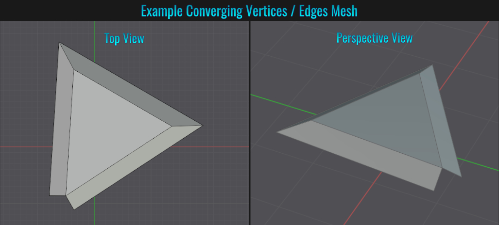
Method 1: Converging Vertices (No Add-Ons)
The trick here is to make use of sliding vertices and auto merging them!
- Start by selecting the example mesh and going into vertex select mode. Next, go to the Options dropdown menu in the upper right hand corner of the viewport and enable both Auto Merge and Split Edges & Faces.
- Now select one of the vertices you wish to converge and press G twice (this will enable you to slide the vertex along its edge). Slide the vertex out well beyond what would be the convergence point! Repeat this same step with the other vertex.
- Once you left click to place the second vertex, you'll notice that a third vertex is automatically inserted at the projected convergence point of the two outer edges! Finally, select this newly converged vertex, then hold Shift and select each of the extended vertices, press M (to bring up the Merge menu) and choose First. Voila! With the extended vertices merged into the new central one, you now have a completed projected convergence result!
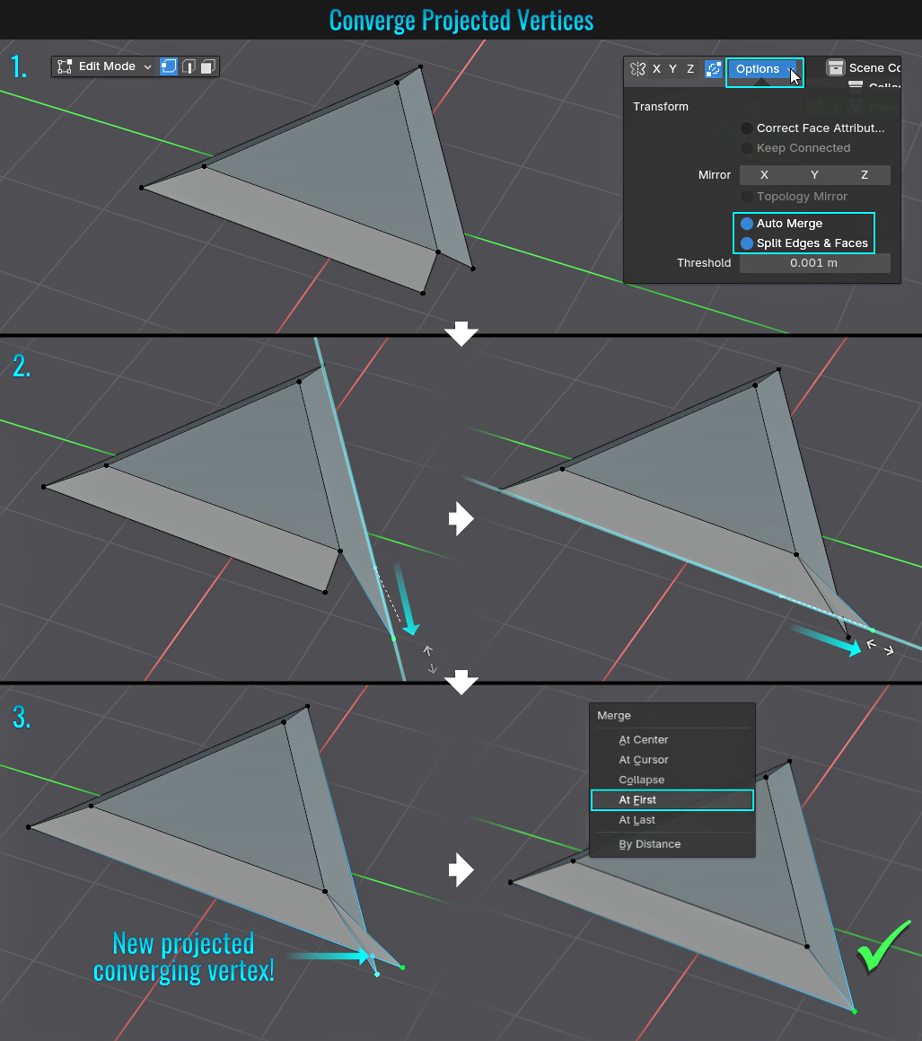
Method 2: Using TinyCAD Add-On
This method is much quicker than the first one, as it makes use of an add-on that is already included with Blender!
- The first thing you need to do is go into Edit > Preferences from the top menu and from there, select Get Extensions from the preferences side bar. In the top search field, type tiny. Find and enable the TinyCAD add-on. Then in the Add-on panel, enable it.
- Next, select the mesh, go into Edit Mode and choose Edge Select. Select the two edges that need coverging, right-click and choose TinyCAD > VTX | Auto from the mouse menu! The result will be added edges that converge!
- Finally, go into Vertex Select mode, Choose this new central vertex. then hold Shift and select each of the extended vertices, press M (to bring up the Merge menu) and choose First. You now have a completed projected converging result!
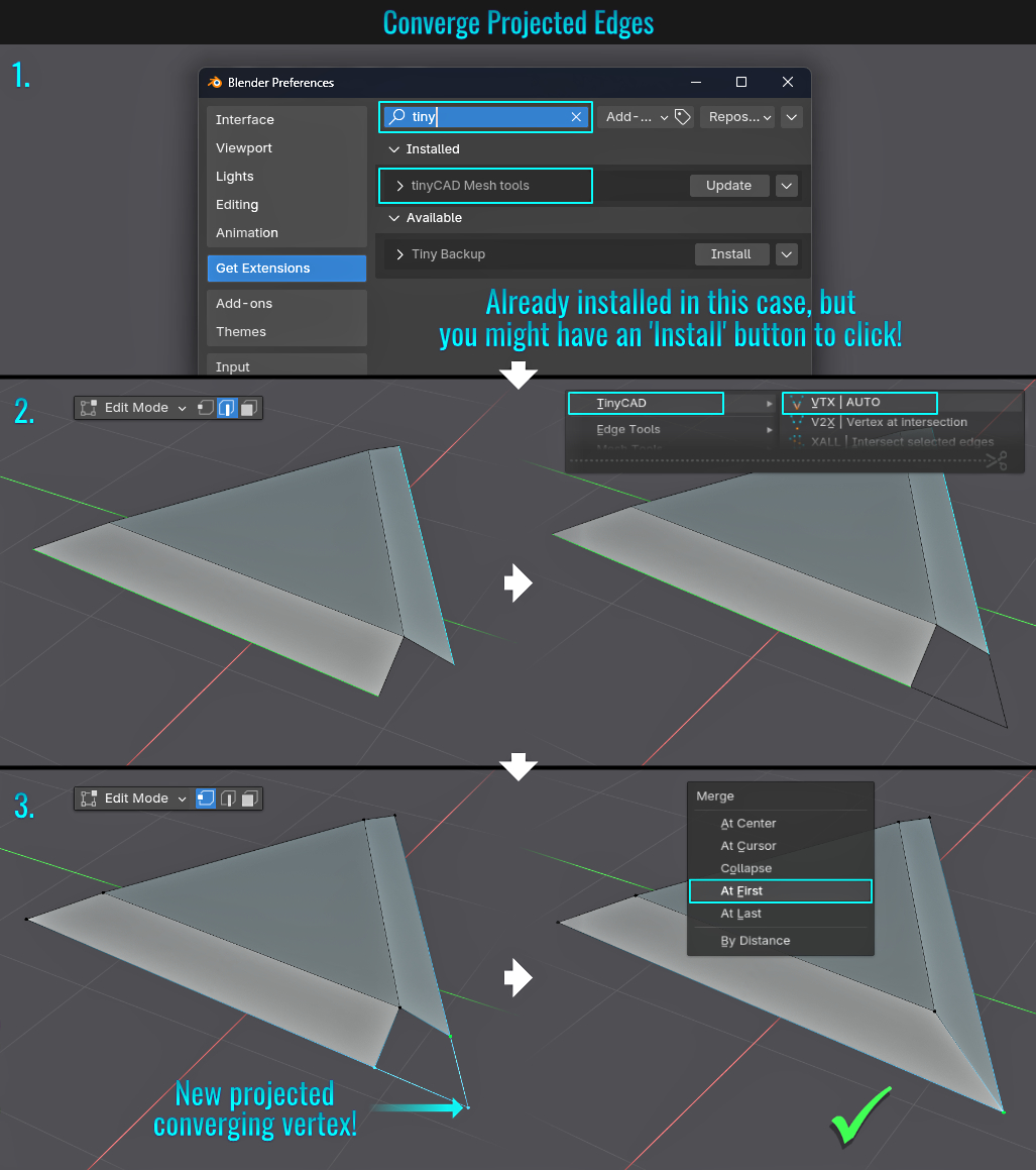
- Open/Close Property Panels Quickly
Rapidly opening or closing a stack of property panels is as easy as simply holding down Shift while click-dragging over the stack to rapdily open (or close) them!
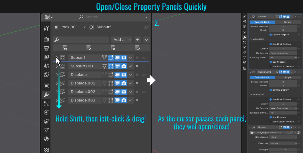
- Place 3d Cursor To Quarter Circle Center
There may be cases in your 3d modelling journey where you need to find the center of a quarter circle mesh (based off of a bevel corner vertex for example - no initial full circle was created). To make things trickier, the mesh is off grid and not at world origin! Here are at least two different methods for placing the 3d cursor to its center!
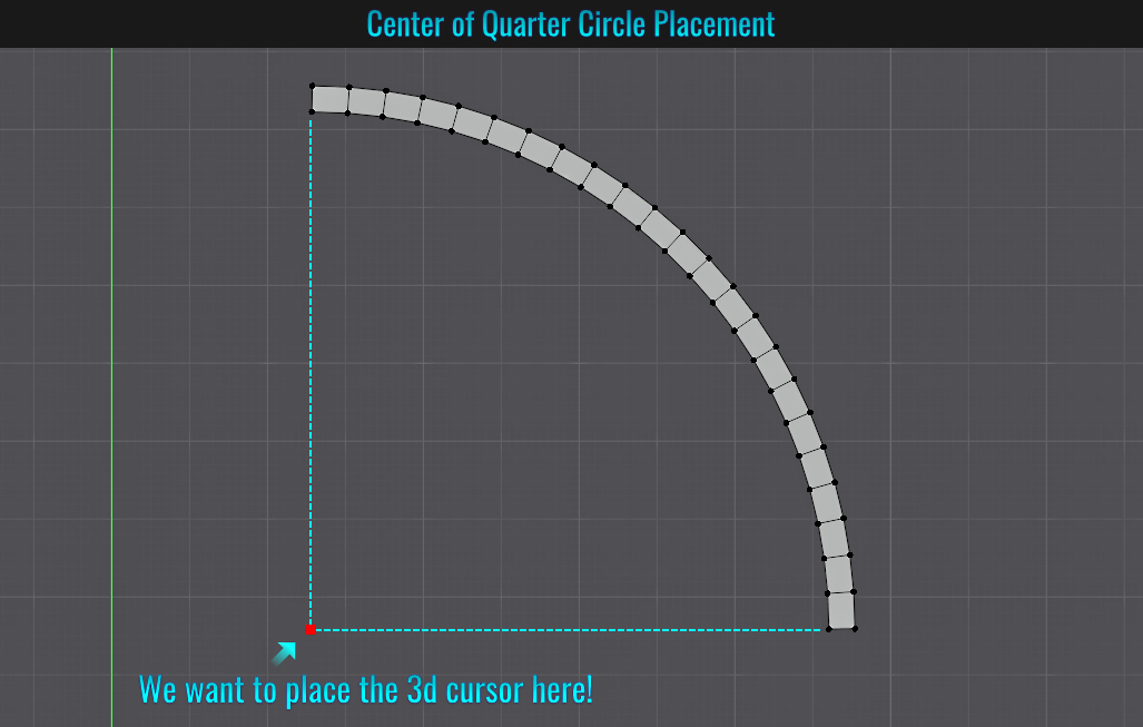
Method 1: Vertex Snapping
- Go to the snap settings dropdown menu (located in the central top part of the 3d viewport) and choose Vertex as the snapping option and click on the magnet icon to enable this snap feature. To ensure that the 3d cursor will be visible in the viewport, navigate over to the Overlays drop down menu and enable 3d Cursor. Finally, click on the Cursor button on the left hand side of the viewport. This will allow you to place your 3d cursor where you left click within the viewport.
- Simply click-drag the 3d cursor over to one of the quarter circle end points (once snapped to the vertex, a green box should appear to visually confirm this) and let go of the mouse button.
- Finally, once again left click to start dragging, then press Y (assuming this is all done in the top orthographic view [7 on the numpad] - if it's another view, press the appropriate axis key that is parallel to that end point's edge) to constrain the 3d cursor and drag the mouse to the quarter circle mesh's other end point. The 3d cursor should be aligned with that vertex while also staying aligned with the original end point's vertex. Done!
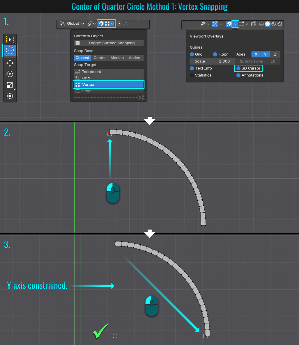
This next version involves duplicating and moving a vertex to the desired location along with moving the 3d cursor to selections. As with the method above, ensure that the 3D Cursor is enabled in the Overlay drop down menu!
Method 2: Vertex Copy
- Start by selecting one the quarter circle mesh end vertices. Then press Shift + S (to bring up the Snap menu) and choose Cursor to Selected. This will in turn move the 3d cursor to the selected vertex.
- Next we need to set up the pivot point. Hit the . (period) key (not on the numpad) and choose 3D Cursor from the resulting pivot point menu. Now select one of the other end point vertices on the quarter circle mesh, press Shift + D to dpulicate it and right click to cancel its transformation. Then press S (to scale), then X to constrain to the x-axis, then 0 to zero the duplicated vertex (which will be using the 3d cursor as the point of reference). The end result is the duplicated vertex vertically aligned with the vertex that it was duplicated from, but horizontally in line with the 3d cursor.
- Finally, with the newly duplicated vertex still selected, once again press Shift + S (snap menu) and again choose Cursor to Selected. Now the 3d cursor is located where the duplicate vertex is! You can delete this unwanted vertex and continue with whatever operations you require involving the quarter circular mesh, all based off the cursor as a pivot point (treated as the mesh's center)!
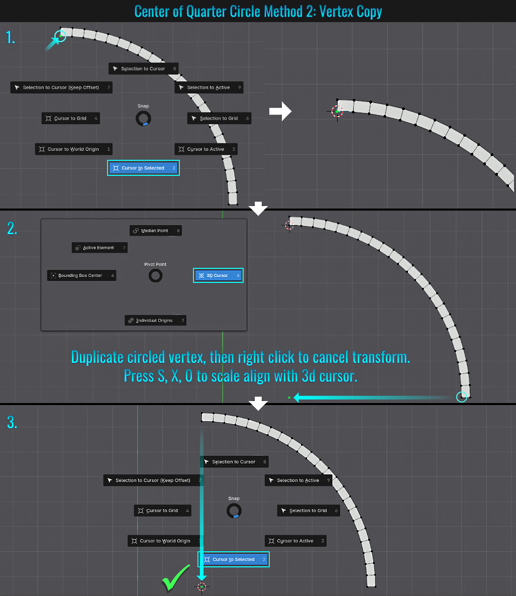
- Bend Using Built-in Shortcut
Starting with a mesh containing enough deformation segments, go into edit mode (vertices, edges or faces), make a selection, simply press Shift + W and start left-click dragging to initiate a bend!
Holding Alt during this bend operation will give a more circular curvature! This bending alternative is destructive modelling (unlike the Simple Deform > Bend modifier)! Holding Ctrl while bending gives snap angle results.
There are a few crucial points to keep in mind when bending meshes this way:
- The bend makes use of the location of the 3d cursor as the pivot point!
- The location of the mouse cursor at the start of the bend will determine the bend effect!
- Once the bend starts, the closer you move the mouse cursor to the 3d cursor, the tighter the bend radius. The further away, the wider the radius!
- This bend operation is view dependent! Best to do this in an orthographic view like top, front or side view!
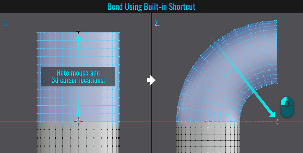
- Recovering Applied Rotations on a Model
This useful trick is for when you have a model that is rotated (could be on multiple axis) and its rotation is applied (meaning that simply pressing Alt + R which normally resets the orientation back to 0,0,0 won't work due to it already being applied) and you wish to re-establish
a defaul zero rotation in all three axis. The catch with this method is that there needs to be two sets of faces on the model (assuming the model was straight and upright), one of which is parallel to the world grid floor and the other perpendicular to one of the grid axis!
Consider the following example and how we'll recover this model's rotation orientations in two simple steps...
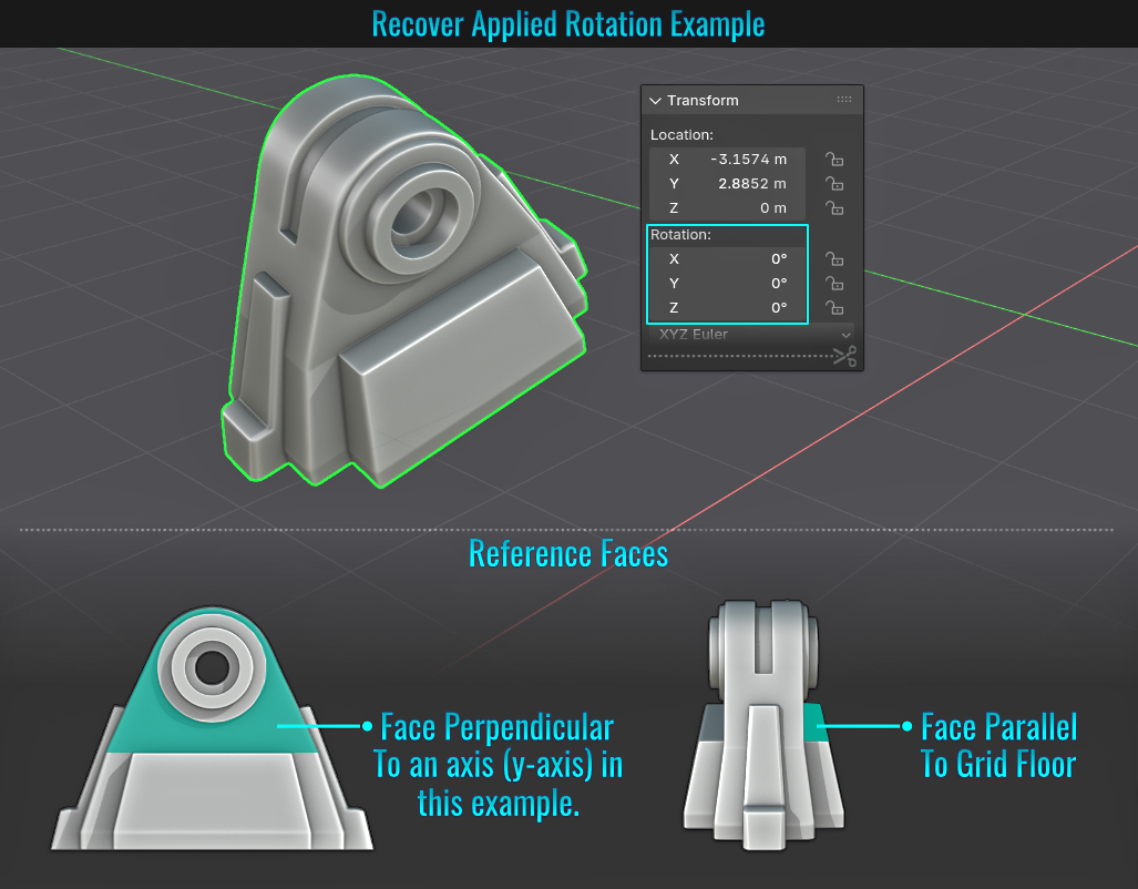
Step 1: Parallel To World Floor Orientation
- In the snap settings (Shift + Ctrl + Tab to bring up the Conform Object menu at your mouse cursor), enable Toggle Surface Snapping at the top (this basically sets the Snap Target to Face and enables Align Rotation to Target). Next, press Shift + A and choose Mesh > Plane to add a plane object to the scene. With the plane object selected, press G, then hold Ctrl (only if the snap icon isn't activated) and click drag it onto the face of the model that would be parallel to the world grid floor. The plane should move to and align with this.
- With everything deselected, first select the model, then press Shift and select the plane. Next, press Ctrl + P (to bring up the Set Parent to popup) and choose Object (Keep Transform). It is important to keep the transform!
- Now only select the plane, press N to bring up the side panel within the 3d viewport and within the side Item tab, select all three rotation values and zero them out!
- Finally, select the model, press Alt + P (to bring up the Clear Parent popup) and choose Clear and Keep Transformation. The model retains its current rotations and the plane object is no longer a parent... The first step is now done, and the model should be parallel to the world floor grid!
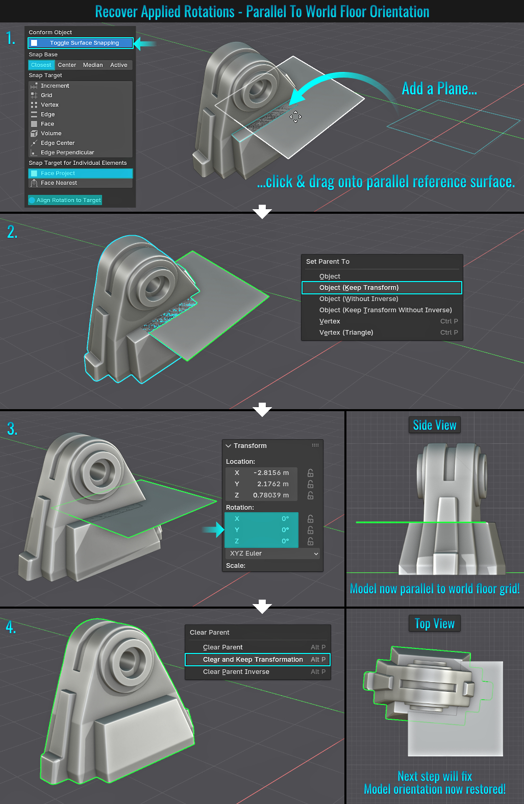
Now that most of the orientation has been fixed, it's time to snap the plane to the other model's reference face and reset that one (in this case the y-axis).
Step 2: Perpendicular To Y-Axis Orientation
- Keeping the previous surface snap settings enabled and with only the plane object selected, hold Ctrl (again, only if the snap icon isn't activated) and click drag it onto the face of the model that would be perpendicular (90°) to the y-axis this time.
- Once again, select the model only, then press Shift and select the plane object. Next, press Ctrl + P (to bring up the Set Parent to popup) and once again choose Object (Keep Transform).
- This time, again with only the plane selected, press N to bring up the side panel and within the Item tab, set the z-axis rotation value to zero! Now the model should be both parallel to the world grid floor and perpendicular to the y-axis!
- Finally, select the model, press Alt + P (to bring up the Clear Parent popup) and choose Clear and Keep Transformation. Delete the plane, select the model and apply its rotations (via Ctrl + A to bring up the Apply Transforms menu - choose Rotation, which will zero out the mesh's current rotation values). The rotation orientations are now restored! No more odd applied baked-in rotations!
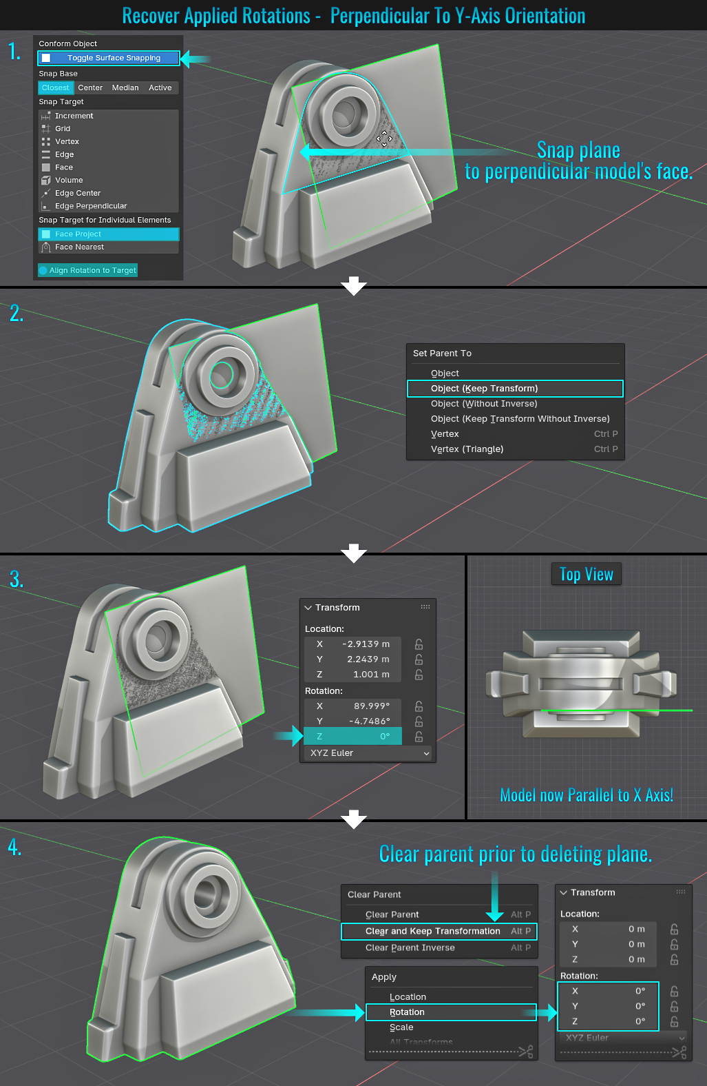
No, this isn't a tip for finding negligent parents who lost their children at a theme park, but rather by selecting any child object, you can find / select the parent (and possibly all other children) as a result! This is kind of related to
tip# 109: Traverse Parented Meshes, but in this case, it is more about adding to a selection more than traversing selections!
In the following example, all pipe peices have been parented to an empty cube object.
- Start by selecting any child object in the scene. Then press Shift and [. Regardles of which child object is initially selected, this will automatically select the parent as acitve while the child is now just selected.
- Now press Shift + ] to select all children parented to the parent object as well!
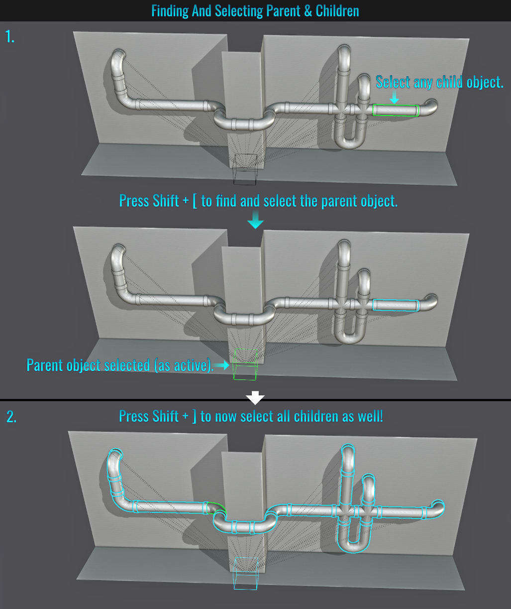
You can easily swap two viewports by simply placing the mouse cursor at the corner of one viewport (the mouse cursor will turn into a white cross), then hold Ctrl and click drag (the mouse cursor will change into two diagonal black and white squares containing double-headed arrows pointing into each square ) into the adjacent viewport. Both of those viewports will swap positions!
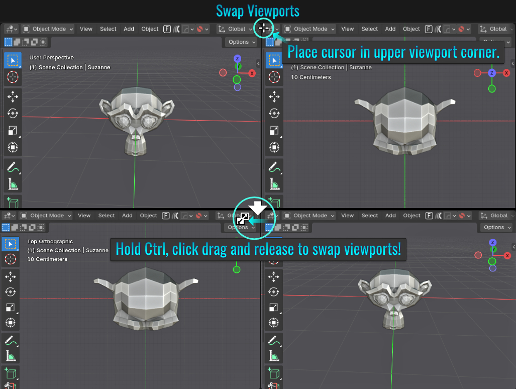
- Bridge Edge Loop Pipe Corner
- When it comes to making pipe corner pieces, it can be eaiser to simply start with selecting two separate pipe pieces and joining them together into a single mesh (using Ctrl + J) and then in face select mode, select the faces of each end of the pipes.
- Now, right-click and choose Bridge Edge Loops. This will join the pipe pieces (albeit not with the results we are looking for yet).
- In the resulting popup in the lower left hand side of the viewport, first adjust the Number of Cuts value to add segments to the corner bend (but it might be the case that the bend is clipping into itself on the underside), and if this is the case, play with the Smoothness value to determine how smooth the corner is!
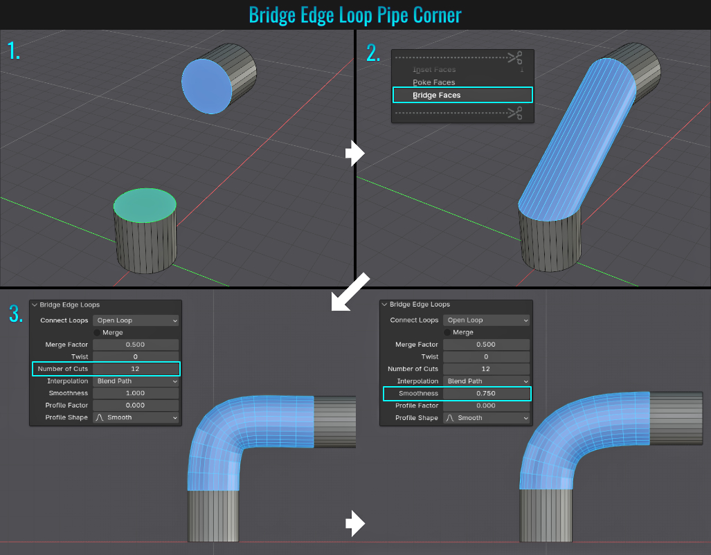
- Rolled Up Mat
Making a rolled up mat is quite easy once you know how! Before starting however, ensure that you have the included Extra Curve Objects add-on enabled!
- Start with making a mat (from a scaled plane) with enough segments for proper deformation (using Ctrl + R, hovering the mouse cursor over one of the long side edges and middle mouse scroll). Once these segments are inserted, you can manually enter the Number of Cuts in the Loop Cut and Slide panel in the lower left hand side of the viewport. Add something like 128 segments for example. Also extrude the mat a bit in the z-axis to give it some thickness, otherwise it will be paper thin and unrealistic (unless the goal is rolled up paper!) Select one of the end edges of the mat, press Shift + S (to bring up the 3d cursor snap menu) and choose Cursor to Selected. This will insert the 3d cursor to the center of the selected edge.
- Next, deselect the mat, press A and choose Curve > Spirals > Archemedian. In the resulting Curves Spiral popup, play around with settings like Turns, Radius Growth and Radius until it resembes the shape of a rolled up mat. While in Edit Mode, rotate the curve along the Y axis (via pressing R then Y then typing 90 and hitting enter.)
- Finally, with the mat object selected, click on the modifier tab and choose Deform > Curve. Within the Curve modifier, choose the spiral curve object from the Curve Object dropdown menu! Voila! The mat is rolled up. Feel free to right-click on the mat object and add a Shade Auto Smooth to it and scale the spiral curve to adjust the rolled up effect a bit!