Monday October 26th, 2026
Plasticity Tips & Tricks

Last updated: September 13th, 2026
Plasticity is a modern, robust, and artist-friendly 3D NURBS-based CAD application designed for artists across multiple disciplines who need to create complex, high-quality surfaces efficiently without the overhead of traditional engineering software. It emphasizes speed and flexibility through a direct modeling approach, offering an intuitive user interface and a hotkey-driven workflow similar to Blender. This section includes a wide range of useful and sometimes underutilized features!
Recent Updates
August 24th, 2026
August 19th, 2026
August 16th, 2026
Modified tip #14: Copy Bevels to Selections with an image and bullet points.
August 15th, 2026
August 14th, 2026
August 13th, 2026
Modified tip #13: Stopped Fillet/Bevel with renaming it, adding an image and bullet points.
Subject
Description
- Taper Face
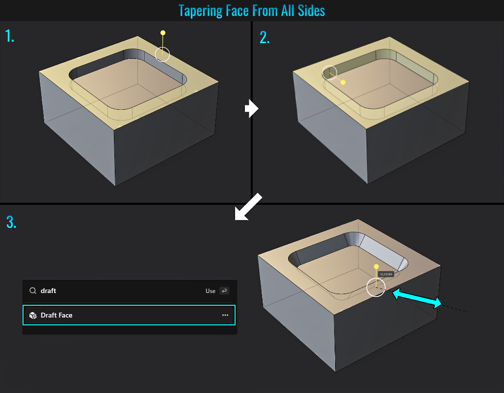
Tapering Face From All Sides
In Plasticity, tapering isn't as simple as selecting a central face and scaling it! To do this, you'll need to:
- First, select a reference face (by pressing 3) and selecting (usually) a nearby adjacent perpendicular faces you wish to taper.
- Next, hold Shift+Alt and click select the connecting perpendicular faces.
- Finally, press F (to bring up the command palette) and search for Draft Face. Once executed, click and drag the white circle component of the gizmo and taper the perpendicular faces!
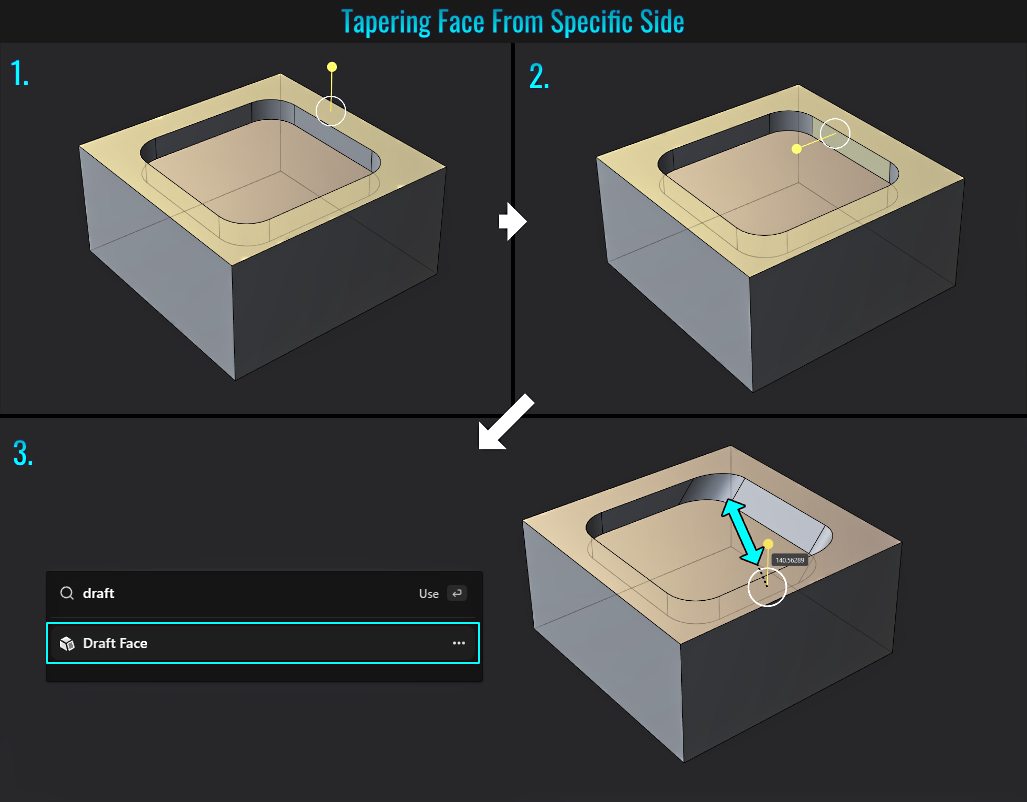
Tapering Face From Specific Side
If you only wish to taper a side of something more complex, you can simply:
- First, select a reference face (by pressing 3) and selecting (usually) a nearby adjacent perpendicular face you wish to taper.
- Next, hold Shift and click select the side perpendicular face you wish to taper.
- Finally, press F (to bring up the command palette) and search for Draft Face. Once executed, click and drag the white circle component of the gizmo and taper the perpendicular face!
- Add to Favorites
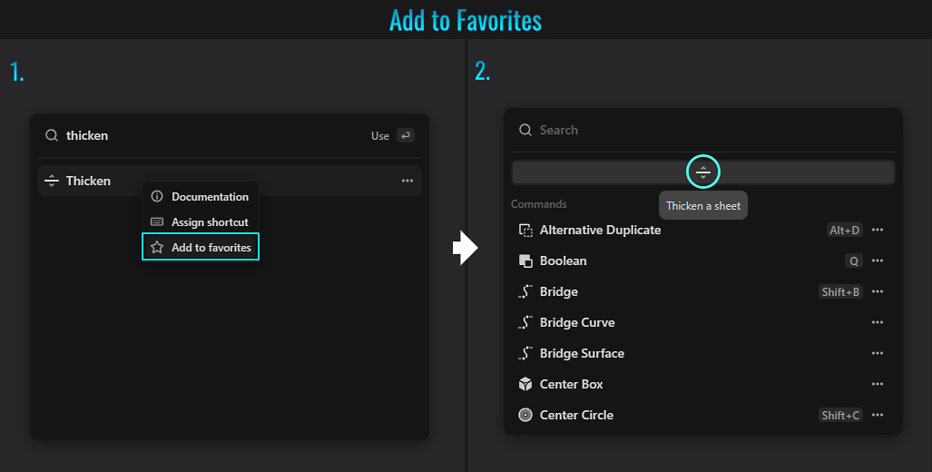
- When listing commands from the command palette (by pressing F) that you intend to use often, you can simply right click on the desired command and choose Add to Favorites.
- This will add that tool icon along the top of the command palette header bar for fast access to frequently used tools! Of course, in the right-click popup, there is also the option to bind keyboard shortcuts as well!
- Trimming Curves & Lines
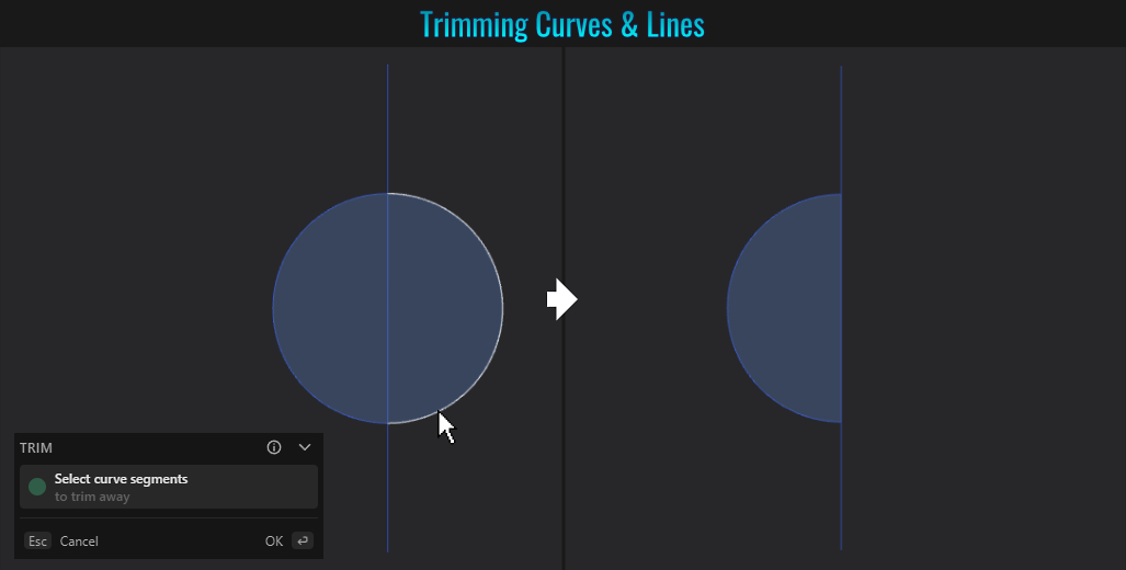
You can trim curves/line segments by simply pressing T (for trim) and clicking on a curve (or line) segment to remove it!
- Through Object Selection
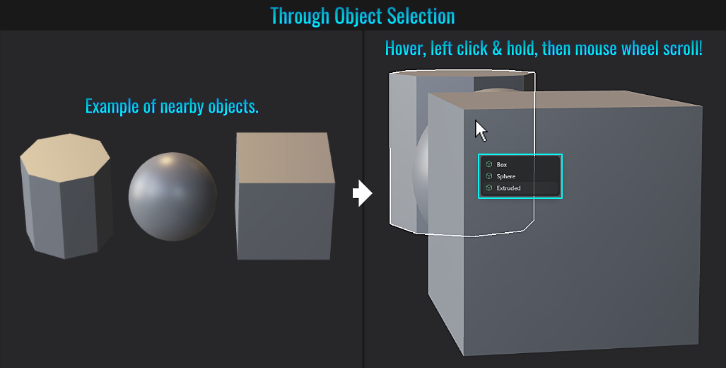
Did you know that you can simply hover the mouse cursor over a foreground object, left click but hold the button down and scroll the middle mouse wheel to select through objects behind it? You'll even have a mini popup list of objects and the current selected object highlighted! Once you find the object you wish to select, simply let go of the left mouse button and voila! That highlighted object from the list is now selected. You've in essence cycle selected through objects in the viewport without needing to select it via the outliner!
- Complete vs Partial Selections
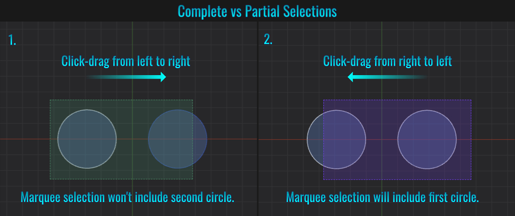
When it comes to marquee selecting objects, the direction of the click-dragging action will determine whether they will be selected or not!
- If you left click and drag from left to right, the marquee region should appear tinted green (assuming default colours). This means that you must completely cover the object(s) you wish to select. If even a small portion of an object remains outside this marquee, it will not be selected!
- By contrast, if you left click and drag from right to left instead, the marquee colour will be tinted purple and any object that this touches will be automatically considered selected!
- Duplicate & Align
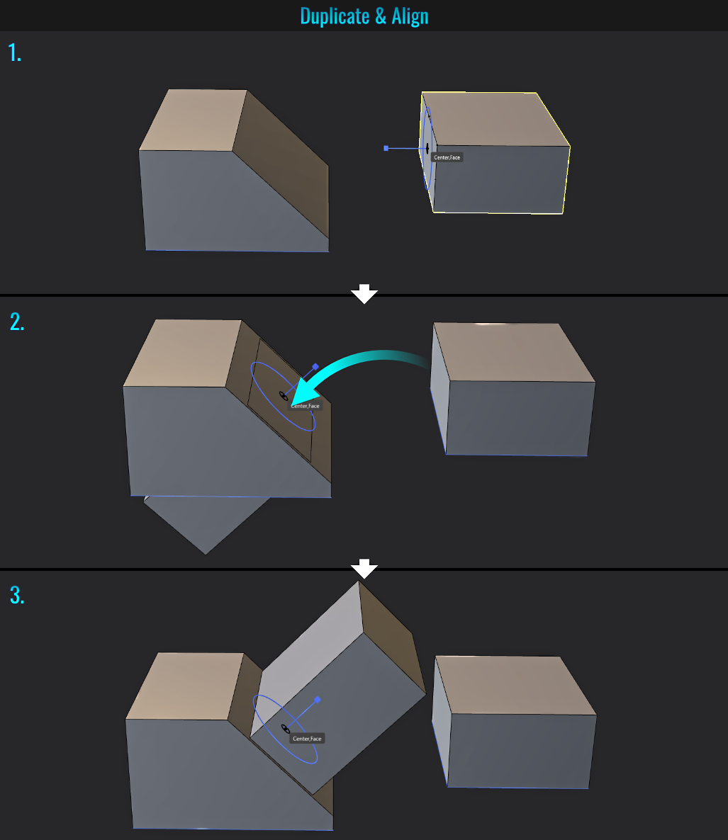
It's pretty easy to duplicate and object and align it to another one.
- Start by selecting the object you wish to duplicate and press Ctrl + D. At this point, Plasticity is expecting the user to click on a face of the selected object to be duplicated (as denoted by the blue gizmo that shows up once the mouse cursor is close enough to the object in question). Strategically click on the object's desired selection (usually center bottom or side face for instance).
- Next, hover over the target surface of another object.
- If the orientation of the newly duplicated object is not correct, press F to invert it. Finally, left click where you want to place it and either right-click or press Enter to finalize it!
- Isoparam
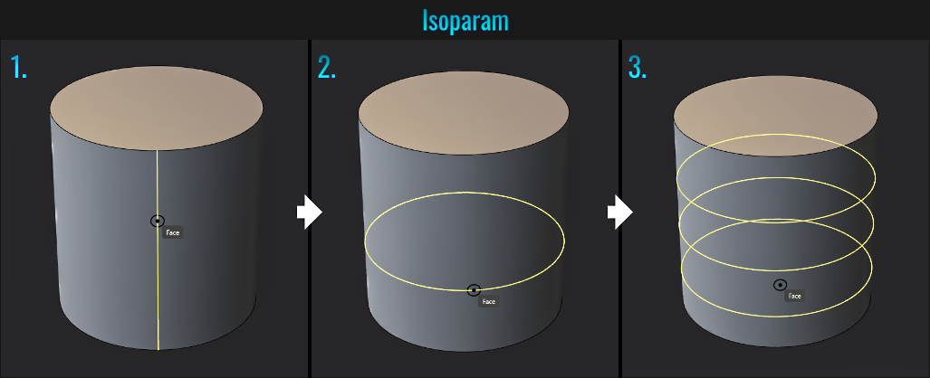
Much like in Blender, you can add some line segments to a surface by first hovering over a face (regardless of which selection mode you are in).
- Press Ctrl + R. A segment line will appear at the mouse cursor.
- There is the option of toggling between vertical and horizontal lines by pressing Tab while the isoparam tool is live.
- You can also hold Shift and use the middle mouse button to scroll up or down to add or subtract extra segments respectively!
Finally, left click to finalise the placement of the segment(s).
- Change Circle Orientation
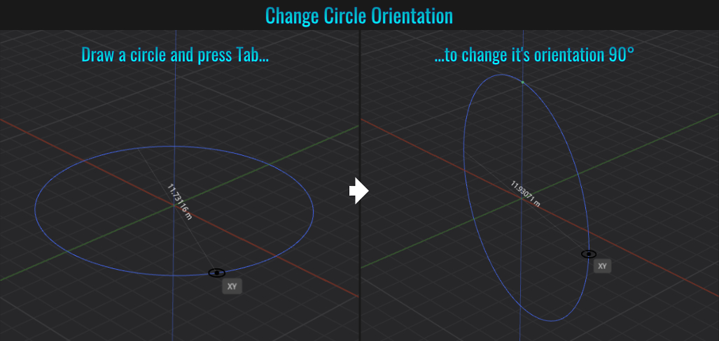
When drawing a circle in say front or side view, before left clicking to finalise this shape, press V to change its orientation 90 degrees. This is useful when drawing a circle based off of blueprints for instance. Given the image's line density, it might not be practical to try and get a circle properly sized from top view, but is manageable from the side! The only other shape that supports this feature seems to be the polygon tool.
- Construction Lines
Aligning One Segment Point to Another
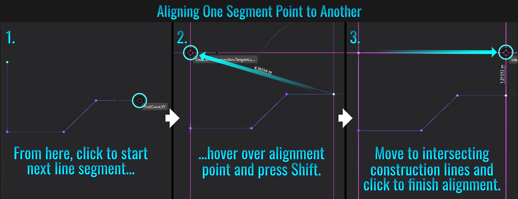
When drawing out shapes with the line tool for instance, it is possible to align your next line segment (which requires to be aligned with a certain source point) by:
- First, at the end pf the current line segment, hover the cursor over said alignment point.
- Next, tap Shift. This will generate X and Y construction lines from both the latest point you added and the alignment point.
- Finally, hover over the newly created intersecting construction lines and left-click. This latest point will now be aligned horizontally to the alignment point!
Aligning Segment Angle to Another
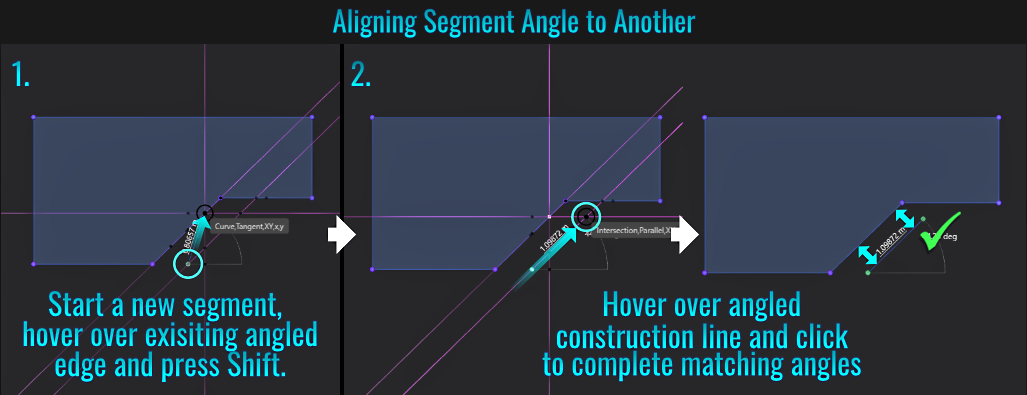
It is also possible to align a new curve line segment's angle to another one, but this time you'll hover over the desired existing segment's edge instead.
- Start a new curve line segment of a new shape (by clicking a starting point) and hover your mouse cursor over a nearby shape's edge that has an angle that you wish to replicate and tap Shift.
- You'll notice new construction lines that follows this edge as well as a parallel one from the new point you created. Now simply hover your cursor over this angled construction line along the new point at the desired distance and click again to form a new edge segment that follows the previous curve's edge!
- Equal Sized Radii
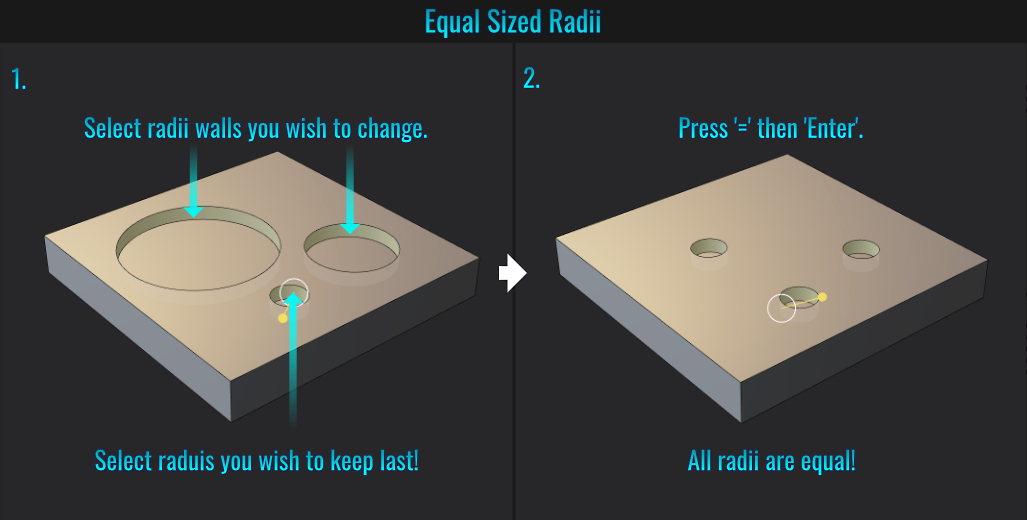
Say you have multiple difference boolean cylinders of varying radius sizes in a surface, and the goal is to make all the radii equal.
- First press 3 to enter face mode, and start by selecting the boolean wall of one of the cylinders where the size of its radius needs to change. Next, hold Shift and select any other cylindrical walls you want to change the radius of, and ensure that the final selection is the radius you wish the others to inherit!
- Finally, press = then Enter/Return. All the other cylindrical walls will automatically match the radius of the final selected one! This seems to work with cylinders in general, not just those used as booleans.
- Object to World Origin
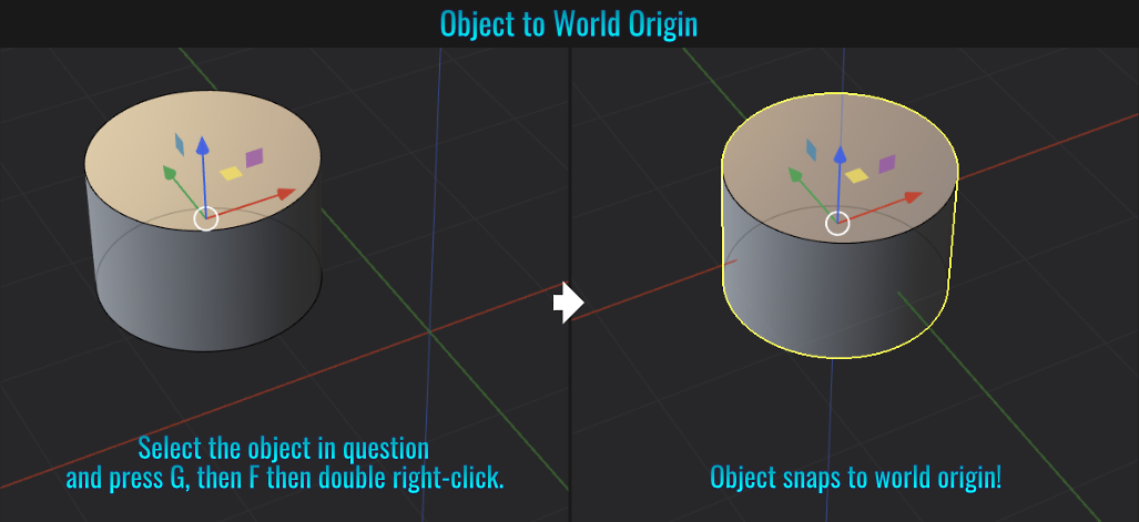
Select an object, then press G then F then double right mouse button click! That object will return to the world origin!
- Copying Edge Fillets
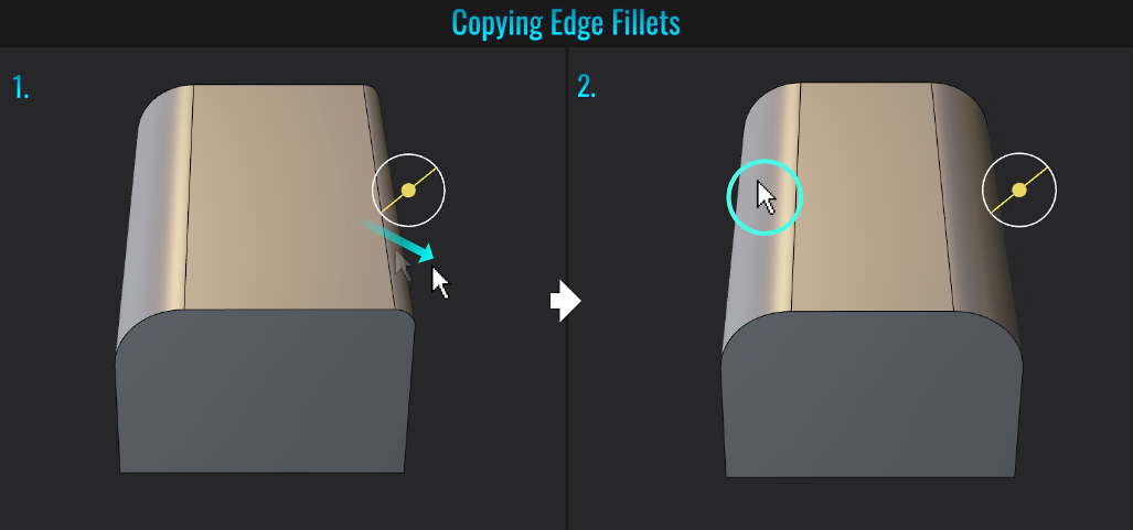
You can copy an existing edge fillet radius to another edge quite easily!
- Start by selecting another edge, press B, start click dragging to create the fillet.
- While the operation is still live, simply hover over an existing desired fillet and click to replicate on the current fillet! This doesn't seem to currently work on chamfers however!
- Stopped Fillet/Bevel
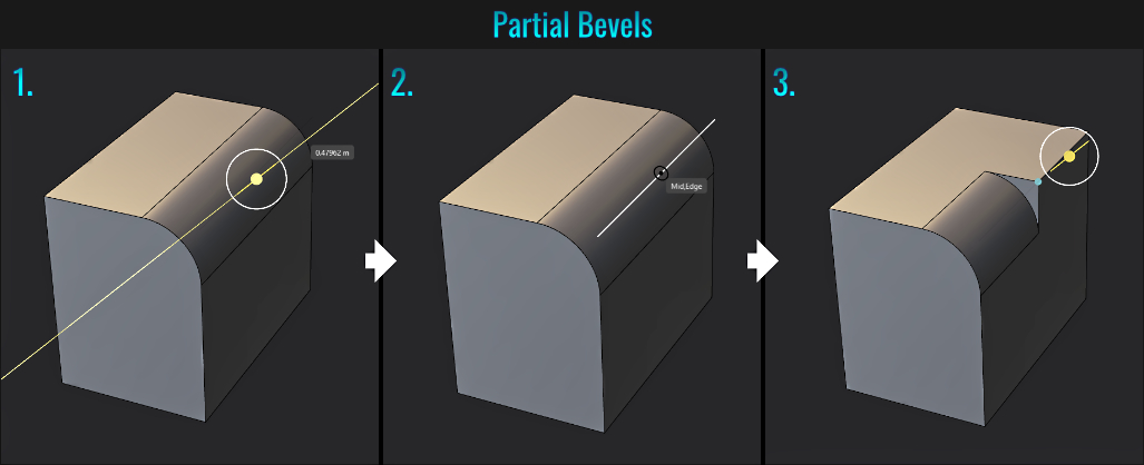
Did you know that after starting a fillet/bevel, it's possible to restrict its length along an edge, thus creating what is known as a stopped fillet/bevel?
- Start be creating a fillet/bevel by selecting the edge, press B and click-drag to establish it (but don't right-click finalize it yet).
- Next, press L. At this point, when you hover the mouse cursor over the location of the original edge, it will become visible. click at any point along it where you wish to terminate the fillet/bevel.
- It will stop at this point (denoted by a small blue dot). The rest of the edge remains like it was prior to adding the fillet/bevel!
- Copy Bevels to Selections
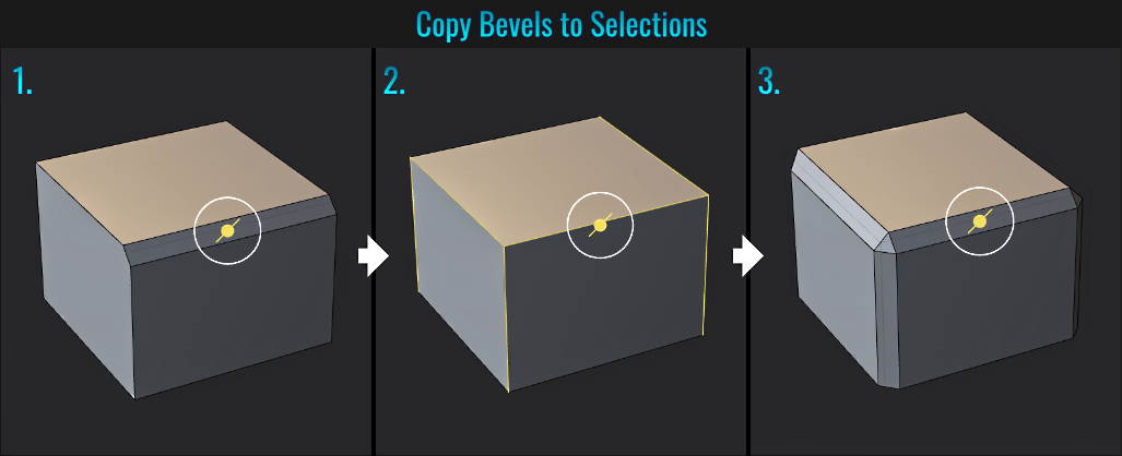
If you have a series of edges you wish to uniformly bevel (but perhaps you're unsure of which ones), you can do this after establishing on bevel (but not finalising it yet) and copy this to other edges.
- With an edge selected, press B and drag out the desired bevel (or fillet as this works as well).
- While the bevel operation is still live, release the left click, then simply hold Ctrl and continue to click other edges (you can even deselect some edges, allowing for a dynamic choice in the matter).
- Once the Ctrl key is released, all the additional selected edges will have the same bevel/fillet as the first edge. Right-click to finalise the bevel operation. Done.
- Variable Fillets
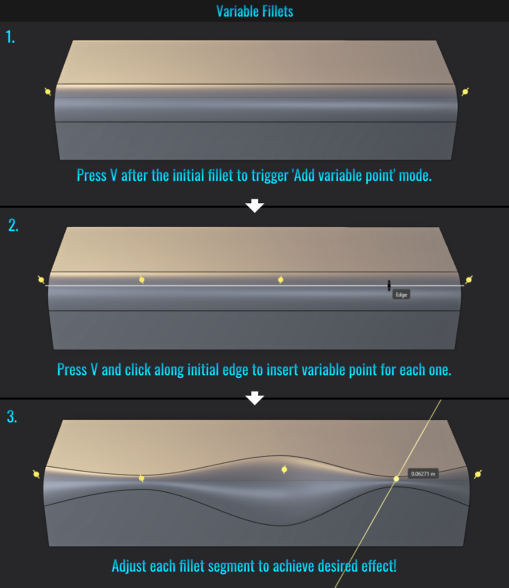
One of perhaps many nifty things about Plasticity is the ability to create variable fillets (though this does't work on chamfers). Here's how to do it!
- Start by creating a fillet (but don't finalize it with via right-clicking just yet) and press V (this enables Add variable point mode). You'll know right away as there are two bevel handles, one on each of the bevels sides.
- Press V again. Notice that the original edge is displayed. At this point, Plasticity is expecting you manually insert a new fillet point by clicking anywhere along this edge (you'll need to keep pressing V prior to each point you insert). Notice that each point has a fillet gizmo.
- Simply adjust each of these gizmos to decide how thick or thin each portion of the fillet is!
- Reconstructing a Circle
Suppose you modelled a curved surface that was based off of a partial circle. Here is a way to recreate a perfect circle from that curved surface.
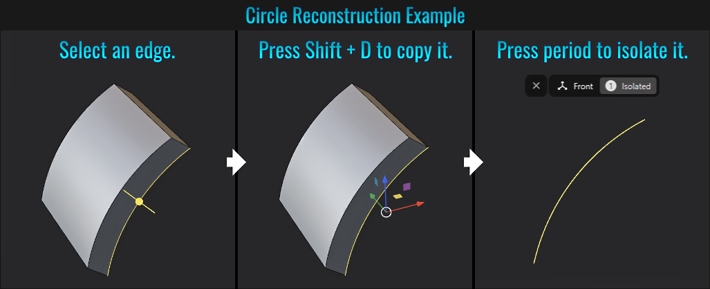
Let's use the following example below as a starting point. The idea here is to select the curved
edge of the surface from which you wish to create a circle from and duplicate it as a sample curve by simply pressing Shift + D. From here, with that newly created curve segment, press . to isolate it for better clarity and
view it from the appropriate orthographic view (in this example, the front view via pressing 1 on the numpad). Your situation might require another view.
Now that we have this starting point done, let's examine how to go about reconstructing a circle.
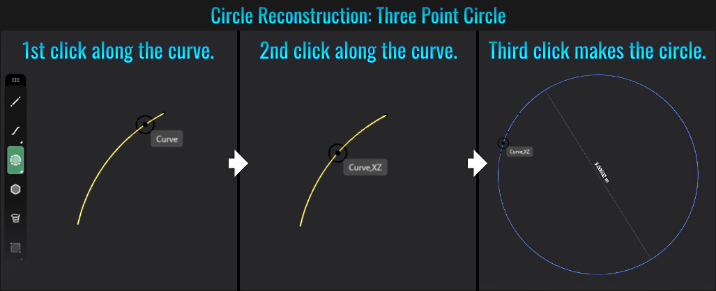
- First, select Three Point Circle from the curve tools (left click and hold on the circle tool to access this).
- Finally, perform three clicks along sample curve! Right-click (or press Enter/Return) to finalise it. A perfectly matching circle!
- Straighten Model Rotation
You might have a model that has been rotated to some arbitrary angle, and you wish to straighten this model's rotation so it is perpendicular to either the Z or Y axis for instance. With the use of a guide line, this can be easily accomplished!
- First, reference a bottom most corner point on the model (it doesn't have to be a corner per say, but it should be at the bottom/side most point that you wish to use as a sort of 'pivot'). Create a straight straight line that starts at this point and goes straight up! This will become the guide line!
- Next, with the model selected, press R for the Rotate tool, then press F (for freestyle mode) and click at the base of this newly added line. Then make the second click at the opposite top point on the model and drag the rotation until the mouse cursor snaps to anywhere along the guide line! Done! The model should now have its rotation straightened out!

- Draw Curve Direction Slice
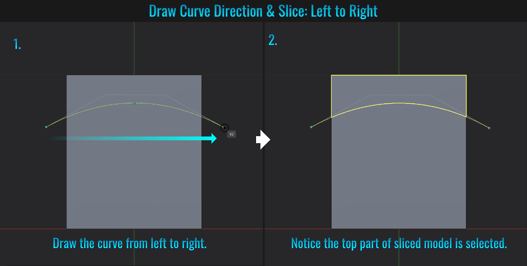
Did you know that the direction you draw a curve prior to slicing a model will determine whether the top or bottom part of the model is selected?
Left to Right
- Draw a curve that you'll use to slice the model from left to right. Right-click to finalise it. Then press C and click on the model itself and once again right-click to finalise this slice.
- You'll notice that the top part of the sliced model is selected!
Right to Left
- Draw a curve that you'll use to slice the model from right to left. Right-click to finalise it, then press C and click on the model itself and once again right-click to finalise this slice.
- You'll now notice that the bottom part of the sliced model is selected!
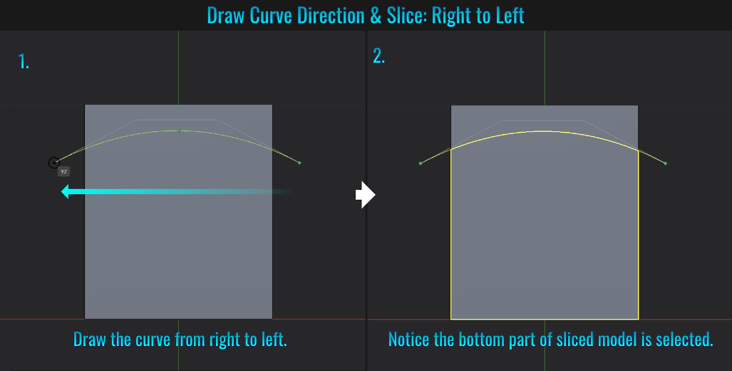
Knowing this, you can strategically auto select which one you need (top or bottom) from the slice operation through the draw direction of the the curve!